
Compact circular saw

a circular saw and compact technology, applied in the field of circular saws, can solve the problems of increasing the difficulty of operating such a machine, affecting the balance of the whole machine, and incompatibility of the whole machine, and achieves the effects of reducing the lateral width of the whole circular saw, compactness, and good gravity distribution

Inactive Publication Date: 2011-08-04
CHERVON LIMITED
View PDF16 Cites 29 Cited by
  • Summary
  • Abstract
  • Description
  • Claims
  • Application Information

AI Technical Summary

Benefits of technology

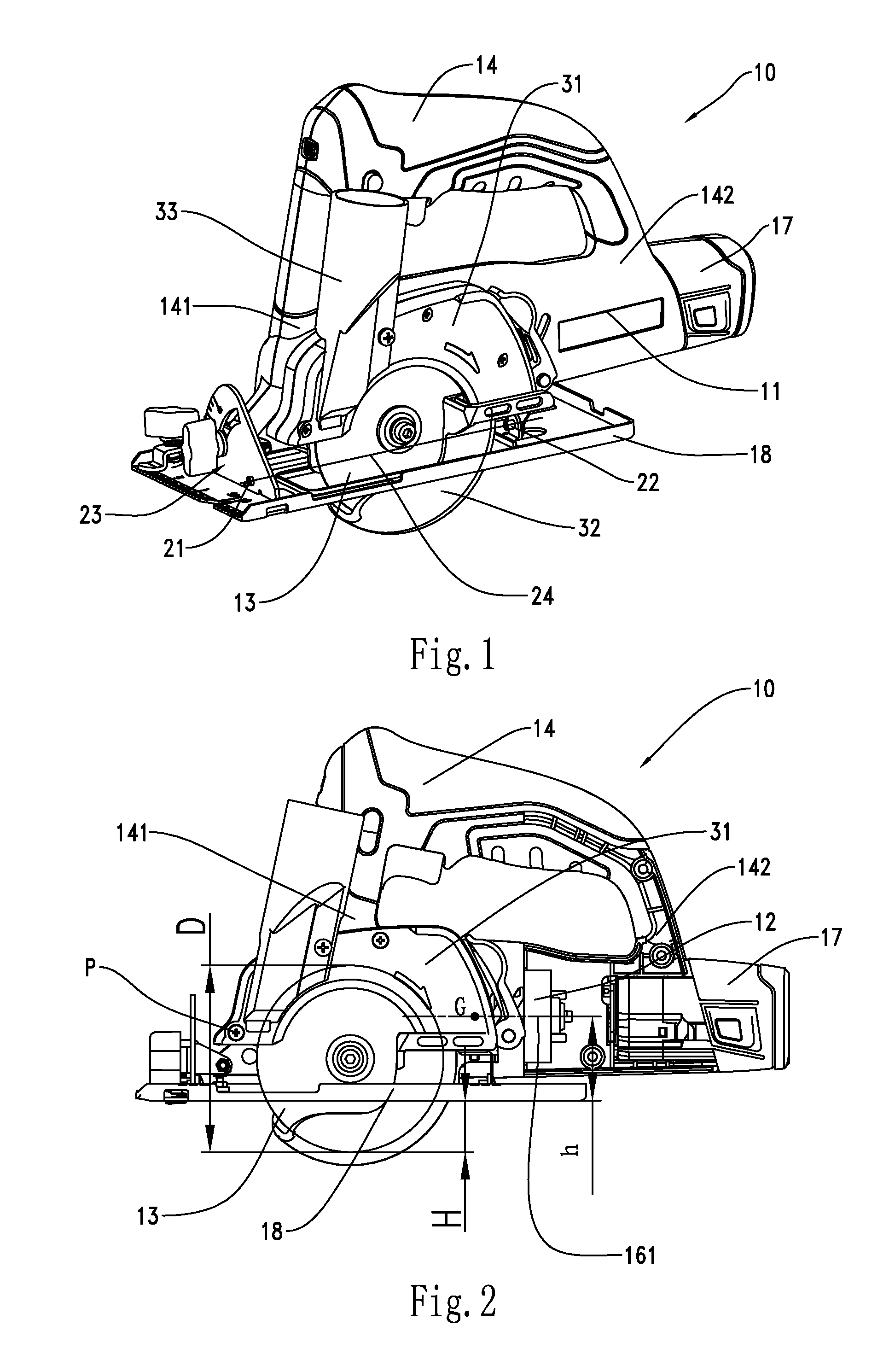
[0005]As will become apparent from the description that follows, by arranging the motor to be parallel or coplanar to the circular blade and by restricting the circular saw within the range of the width of the base plate, the lateral width of the whole circular saw is decreased so that the circular saw is more compact. Moreover, a good gravity distribution is achieved by laterally restricting the circular saw within the range of the width of the base plate. The balance of the whole circular saw and the operability during cutting is thus greatly improved. For example, when the circular saw so constructed is placed in a position of a maximum cutting depth, the gravity of the motor is placed within a range from the base plate to a D / 2 distance above the base plate and the balance of the whole circular saw becomes better with the aid of the motor having a lower center of gravity making the machine easier for a user to hold during the cutting procedure.

Problems solved by technology

The motor is usually arranged perpendicular to the circular blade and located on one side of a plane in which is located the circular blade and, as such, the mass of the circular saw is not distributed evenly thereby damaging the balance of the whole machine.
As a result of this arrangement, a user must continually adjust the strength and direction of the force applied to the handle during a cutting operation to maintain a cutting line in the initial plane of the blade, which thereby increases the difficulty of operating such a machine.
Moreover, when the motor is arranged at one side of the circular blade in this manner, the whole machine is heavy and incompact for the user owing to size of whole machine being large in the direction of the width of the base plate.

Method used


Image

  • Compact circular saw
  • Compact circular saw
  • Compact circular saw

Examples


Embodiment Construction

[0022]FIGS. 1-5 illustrate a circular saw 10 of a preferred embodiment constructed according to the disclosure that follows. The circular saw 10 comprises a housing 11, a motor 12 mounted in the housing 11, a circular blade 13 having a diameter D that is driven to rotate by the motor 12, and a handle 14 mounted on the housing 11. The circular saw is a small-sized, compact portable tool, for which a blade of small diameter less than 100 mm is usually used.

[0023]The circular saw 10 further comprises a power supply device for supplying power to the motor 12. In a preferred embodiment, a battery pack 17 is used to supply power to the motor 12 and is mounted behind the motor 12 so as to have a linear relationship with the motor 12. In other embodiments, the motor could be supplied with AC power by a power cord. Additionally, the connection between the battery pack 17 and the housing 11 could be of the inserting type or the sliding type. For the connecting manner of the inserting type, a ...


PUM

PropertyMeasurementUnit
Angleaaaaaaaaaa
Diameteraaaaaaaaaa
Poweraaaaaaaaaa

Abstract

A circular saw includes a housing, a motor having a rotating axis and a center of gravity on the rotating axis, a handle, a circular blade, a fixed guard, and a base plate having a width supporting the housing. The motor and the circular blade are parallel or coplanar with respect to each other and the circular saw does not extend beyond the width of the base plate in the width direction.

Description

RELATED APPLICATION[0001]This application claims the benefit of CN 201020104874.9 filed on Jan. 29, 2010 which application is incorporated herein by reference in its entirety.BACKGROUND[0002]This disclosure generally relates to circular saws and, more particularly, relates to a compact circular saw.[0003]Traditionally, a portable circular saw comprises a housing, a motor mounted in the housing, a handle mounted on the housing, a rotatable circular blade connected with the motor, a fixed guard mounted on the housing and covering an upper part of the blade, a base plate for supporting the housing thereon, and a movable guard pivotally mounted to the housing and covering a lower part of the blade which extends out of the base plate. The motor is usually arranged perpendicular to the circular blade and located on one side of a plane in which is located the circular blade and, as such, the mass of the circular saw is not distributed evenly thereby damaging the balance of the whole machin...

Claims


Application Information

Patent Timeline
IPC IPC(8): B23D45/16B25F5/02
CPCB25F5/02B23D45/16B27B9/00B27B9/02B23D47/12
Inventor XING, LIZHANG, YIBAOZHANG, FENG
Owner CHERVON LIMITED
Learn More