
Method and Apparatus for Imaging of Features on a Substrate

a technology of features and substrates, applied in the field of methods and apparatus for the imaging of features on a substrate, can solve the problems of high cost, inability to scan, and inability to meet the requirements of scanning, so as to speed up the processing steps, reduce the amount of data, and reduce the size

Inactive Publication Date: 2011-07-21
INST PASTEUR KOREA
View PDF7 Cites 3 Cited by
  • Summary
  • Abstract
  • Description
  • Claims
  • Application Information

AI Technical Summary

Benefits of technology

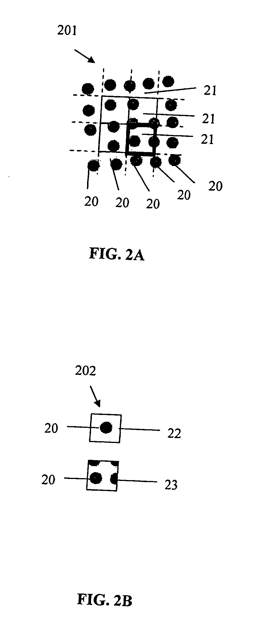
[0010]The inventive method allows for an independent scanning of the substrate in a single or several scanning steps irrespective of the locations of the features, while the locations of the features are identified by using a grid model that is placed on the image. The grid model is preferably a set of points connected by edges, wherein each point of the grid model is assigned a feature on the substrate, i.e. the number of points of the grid model equals the number of relevant features on the substrate. When overlaying the grid model on the scanned image the locations of the points of the grid model initially do not correspond to the actual locations of the features on the substrate. A subsequent fitting of the grid model to the locations of the features on the image allows for the precise determination of their locations and for the extraction of partial images of the features at and around the identified locations for further analysis. Due to the fitting of the grid model to the features of the image a scanning process that includes repeated scanning steps is not necessary. Hence, the demands to the scanner are reduced. Furthermore, the time for the entire imaging process is reduced, since time consumed during repeated displacement steps of the scanner can be avoided.
[0015]According to yet another embodiment it may also be of advantage to treat the image of the substrate, in particular, if multiple images have been produced during the scanning procedure. In particular their size may be reduced before the fitting of the grid model. The size reduction, on the one hand, speeds up further processing steps due to the reduced amount of data that needs to be processed and, on the other hand, a size reduction corresponds to a Gaussian smoothing of the image and therefore reduces noise in the image.
[0016]In another embodiment the image is further processed before the fitting of the grid model comprising one or several of the processes of an application of filters, smoothing, edge enhancement, color adaptation, and the like. A utilization of one or several of these methods helps to further distinguish the feature characteristics in the image, for example smoothing could be used to reduce the noise in the image, or edge enhancement could be used to emphasize the borders and the texture of the features. Selective color enhancement could be applied to enhance the contrast of a feature that has specific color characteristics.

Problems solved by technology

This common technique is limited in several aspects.
Accordingly, the scanning requires a highly precise and correspondingly expensive hardware.
The scanning may fail in case of a lack of precise positioning data or in case of a misalignment between the scanner and the substrate.

Method used


Image

  • Method and Apparatus for Imaging of Features on a Substrate
  • Method and Apparatus for Imaging of Features on a Substrate
  • Method and Apparatus for Imaging of Features on a Substrate

Examples


Embodiment Construction

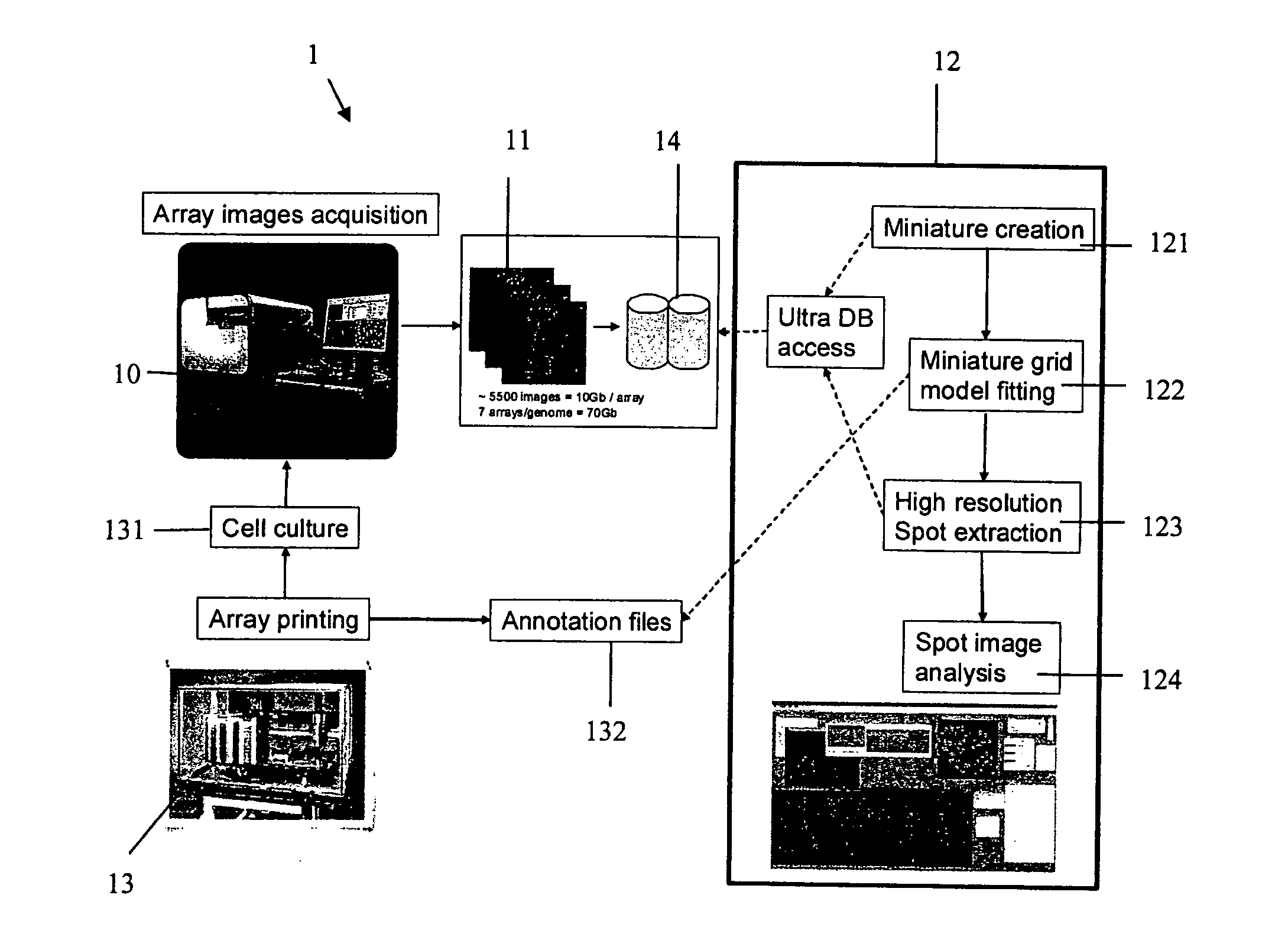
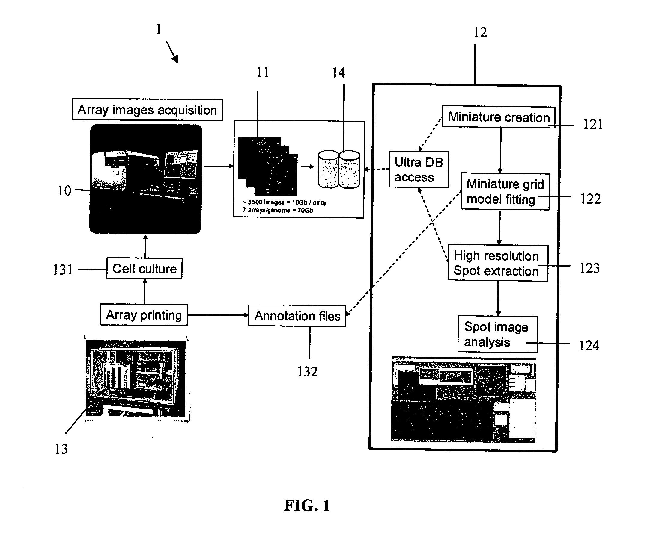
[0036]FIG. 1 shows an embodiment of an imaging apparatus 1 according to the present invention comprising an image acquisition device 10 for producing images of a substrate 11, an analysis device 12, a printer 13 and a data base 14.

[0037]The substrate 131 containing a large quantity of features is scanned with the image acquisition device 10 irrespective of the position of the features resulting in a single image or multiple partial images of the substrate 11.

[0038]For example, a scanning of a substrate 131 comprising a micro array with 3888 spots using a sub-cellular resolution may result in approximately 5500 grayscale images, or approximately 1800 rgb-images. In combination these images may represent the entire surface of the micro array. The images of the substrate 11 are stored in the data base 14 for further processing in the analysis device 12.

[0039]According to the embodiment as shown in FIG. 1 the analysis device 12 first accesses the data base 14 and reduces the resolution ...


PUM


Abstract

A method for imaging features on a substrate, comprising scanning the substrate and producing an image thereof, overlaying a grid model on the image, fitting the grid model to the locations of at least some of the features on the image, and extracting images of the features.

Description

FIELD OF THE INVENTION[0001]The present invention relates to a method and an apparatus for the imaging of features on a substrate and in particular to a method and an apparatus for the imaging of spots on a micro array.BACKGROUND[0002]The imaging and analysis of features on a substrate is an important task in various technical applications. For example in biochemical analysis it is a common technique to apply small spots of a carrier substance on a substrate according to a predefined pattern. Subsequently, small quantities of different cell materials are added to the spots of the carrier substance and cell growth of the different spots is monitored as a function of time by taking images of the spots on the substrate after certain periods of time and by analyzing features within the images.[0003]The imaging of the features can be facilitated by arranging them on the substrate according to a predefined pattern. Usually, dedicated scanner hardware is used to perform the scanning and th...

Claims


Application Information

Patent Timeline
Patent Type & Authority Applications(United States)
IPC IPC(8): H04N7/18
CPCG06T2207/30072G06T7/0046G06T7/75
Inventor GENOVESIO, AUGUSTEEMANS, NEIL
Owner INST PASTEUR KOREA
Learn More