Modular radiance transfer

a module and radiation transfer technology, applied in the field of computer graphics, can solve the problems of lack of performance characteristics for computing, lack of performance characteristics for video games, and unsatisfactory lighting artist work flow

Active Publication Date: 2011-07-21
DISNEY ENTERPRISES INC
View PDF2 Cites 14 Cited by
  • Summary
  • Abstract
  • Description
  • Claims
  • Application Information

AI Technical Summary

Benefits of technology

[0007]Embodiments of the invention provide a technique for computing indirect lighting for complex scene geometry using indirect lighting data pre-computed for a set of simple, abstract shapes. The pre-computed indirect lighting is then mapped to the actual 3D geometry of the graphics scene. One embodiment of the invention includes a method for computing indirect lighting in a three-dimensional (3D) graphics scene. The method may generally include providing a palette of shapes to represent 3D scene geometry. And for each shape, sampling a plurality of direct lighting states for the shape, generating a lighting prior from the

Problems solved by technology

The indirect lighting is usually pre-computed for the 3D scene geometry, as the techniques currently employed lack the performance characteristics necessary for video games (i.e., they lack the performance characteristics for computing the indirect lighting in real-time for frames of computer-generated animation).
While this approach for pre-computing direct/indirect lighting is capable of generating compelling results, the work flow for the lighting artist is some

Method used


Image

  • Modular radiance transfer
  • Modular radiance transfer
  • Modular radiance transfer

Examples


Embodiment Construction

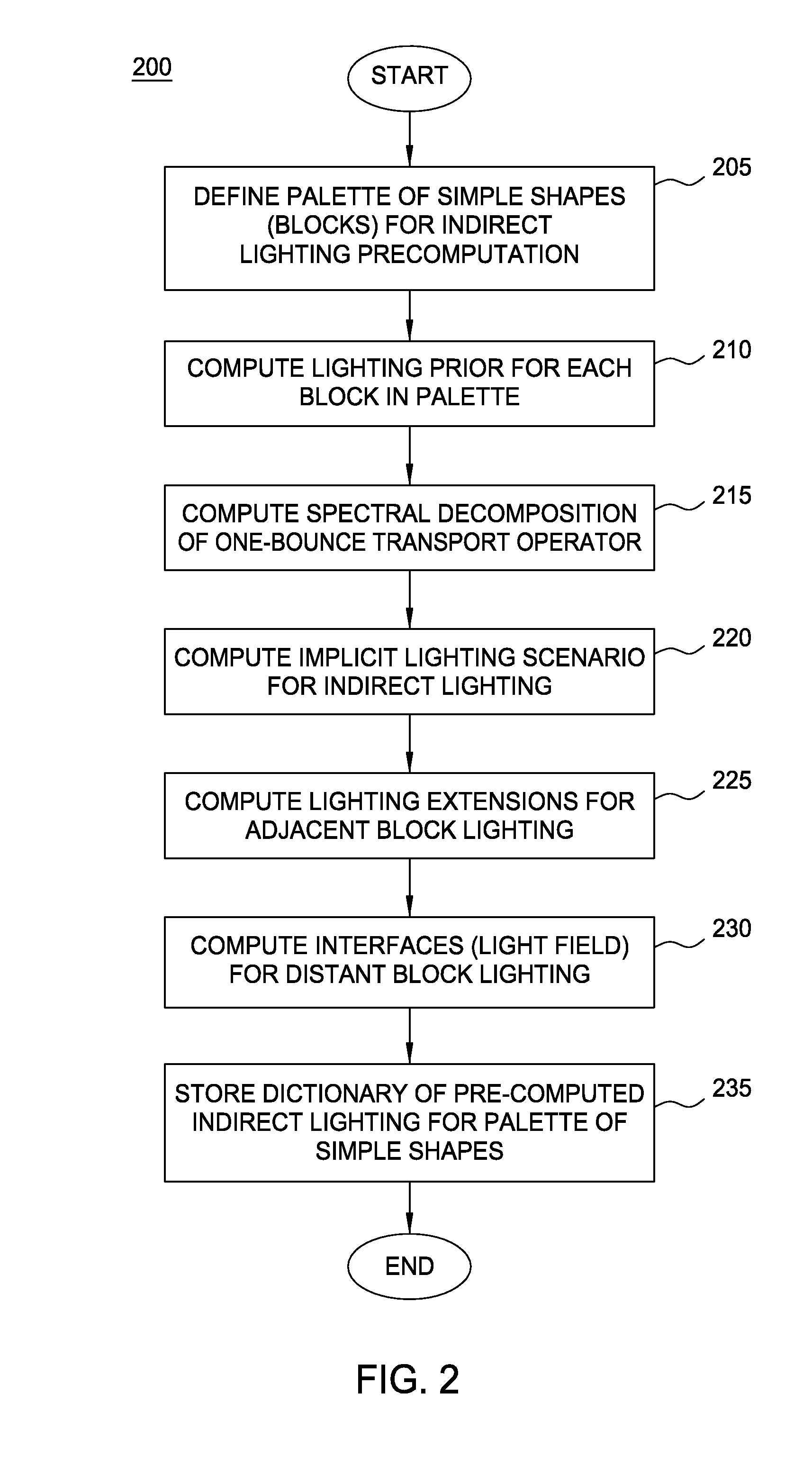
[0020]Embodiments of the invention provide a technique for determining indirect lighting for elements of 3D scene geometry. Indirect lighting generally refers to lighting that does not result from light emanating from a light source, but rather from the “bounce” of direct lighting from a diffuse surface within 3D scene geometry (e.g., a wall or a floor). In one embodiment, rather then evaluate indirect lighting for a particular geometry of a 3D graphics scene, indirect lighting is pre-computed for a set of simple, abstract shapes. The pre-computed indirect lighting is then mapped to the actual 3D geometry of the graphics scene. More specifically, modular radiance transfer pre-computes a spectral decomposition of a one bounce transport operator for each of a set of simple shapes and replaces a scene dependent, direct-to-indirect lighting computation with an art-directable mapping step.

[0021]As described herein, modular radiance transfer provides an approach for rendering an approxima...


PUM


Abstract

Modular radiance transfer pre-computes a spectral decomposition of a one bounce transport operator for each of a set of shapes and replaces a scene dependent direct-to-indirect transfer lighting computation with an art-directable mapping step. Modular radiance transfer provides an approach for rendering an approximate indirect lighting which requires small amounts of data, can be used to model very large (or even random scenes), and propagates much of the indirect lighting using a small number of spectral coefficients, so that rendering scales well to large scenes.

Description

CROSS-REFERENCE TO RELATED APPLICATIONS[0001]This application claims benefit of U.S. provisional patent application Ser. No. 61 / 295,985, filed Jan. 18, 2010 which is herein incorporated by reference in its entirety.BACKGROUND[0002]1. Field of the Invention[0003]The present invention relates to the field of computer graphics and, in particular, to techniques for computing indirect lighting levels present within a computer-generated graphics scene.[0004]2. Description of the Related Art[0005]It is currently common for video games to pre-compute elements of direct or indirect lighting (or both) for a given set of three-dimensional (3D) scene geometry. The pre-computed lighting levels are then used to light elements of the scene geometry at runtime. Typically, pre-computation techniques may be used to render indirect lighting for the 3D scene geometry using an arbitrary direct lighting scenario. The indirect lighting is usually pre-computed for the 3D scene geometry, as the techniques c...

Claims


Application Information

Patent Timeline
IPC IPC(8): G06T15/50
CPCA63F2300/66G06T15/50G06T15/04
Inventor SLOAN, PETER-PIKEANTANI, LAKULISH
Owner DISNEY ENTERPRISES INC
Why Eureka
Try Eureka