
Image forming apparatus, printing system and printing method

Inactive Publication Date: 2011-07-14
KONICA MINOLTA BUSINESS TECH INC
View PDF4 Cites 21 Cited by
  • Summary
  • Abstract
  • Description
  • Claims
  • Application Information

AI Technical Summary

Benefits of technology

[0009]The present invention has been achieved in view of the above problem, and an aim thereof is to provide an image forming apparatus described below, a printing system including the same and a printing method. The image forming apparatus is capable of effectively preventing insufficiency of an amount of money necessary for executing a print job while keeping the print job from being executed until an execution instruction is received.
[0013]According to the present invention, with the above-described structures, when a waiting print job that is kept from being executed until an execution instruction is inputted is received, a budget amount of the billing amount for the waiting print job is allocated regardless of whether the execution instruction of the waiting print job is inputted. Therefore, it is possible to effectively avoid a situation that the waiting print job cannot be executed due to insufficiency of an amount of money for executing the waiting print job during a time between the print job being received and the execution instruction of which being received.

Problems solved by technology

However, in a case where charging for executing a print job is performed and an upper limit of an amount of money for printing that can be used in a predetermined time period is set for a user, the following problem may arise.
That is, because the user causes another print job to be executed and charging for the execution of the another print job is performed while a print job to be executed in the secure print mode (secure print job) is kept from being executed, an amount of money necessary for executing the secure print job is possibly insufficient when the user gives an execution instruction for executing the secure print job.
In this case, the print job cannot be executed.

Method used


Image

  • Image forming apparatus, printing system and printing method
  • Image forming apparatus, printing system and printing method
  • Image forming apparatus, printing system and printing method

Examples


first embodiment

[0036]The following describes a printing system 1 pertaining to a

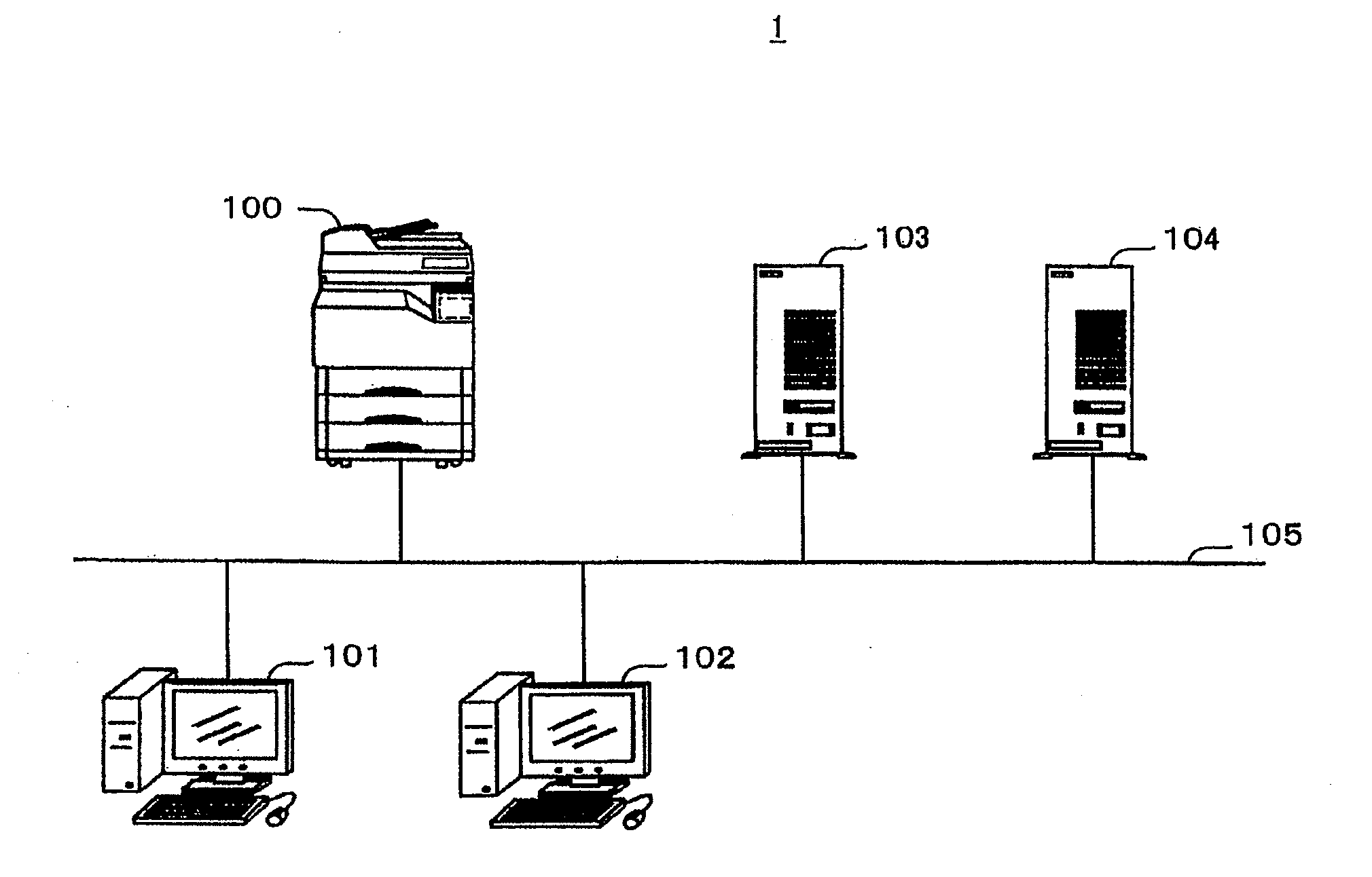
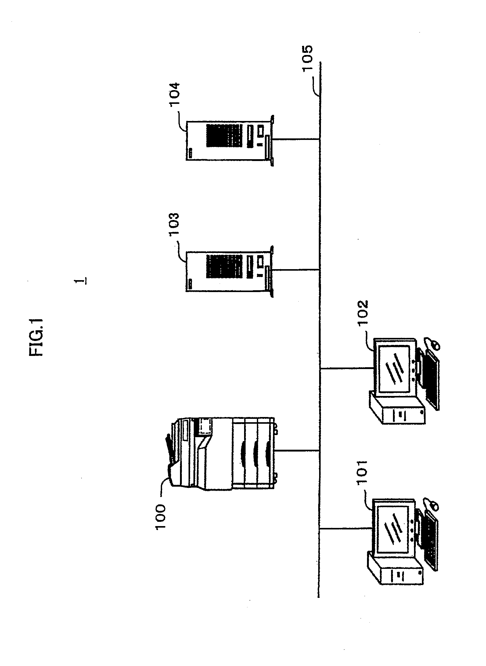
[0037]FIG. 1 shows an exemplary structure of the printing system 1 of the first embodiment.

[0038]As shown in FIG. 1, the printing system 1 is composed of an image forming apparatus 100, personal computers (hereinafter, referred to as “PCs”) 101 and 102, a billing server 103 and an authentication server 104.

[0039]The image forming apparatus 100, the PCs 101 and 102, the billing server 103 and the authentication server 104 are connected to one another via a LAN (Local Area Network) 105.

[0040](2) Structure of Image Forming Apparatus 100

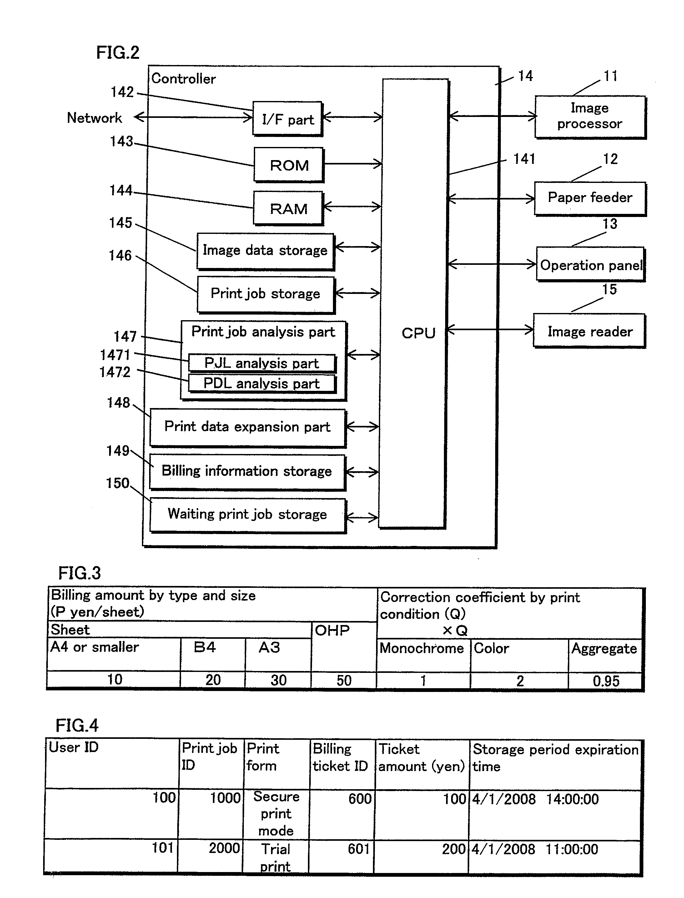
[0041]FIG. 2 is a block diagram showing the structure of the image forming apparatus 100. As shown in FIG. 2, the image forming apparatus 100 is composed of an image processor 11, a paper feeder 12, an operation panel 13, a controller 14 and an image reader 15.

[0042]The image processor 11 performs print processing that forms an image on a recording sheet supplied from the paper feeder 12 ba...

second embodiment

[0128]The following describes the printing system 2 pertaining to the

[0129]FIG. 15 shows an exemplary structure of the printing system 2 pertaining to the second embodiment.

[0130]As shown in FIG. 15, the printing system 2 is composed of a job management apparatus 200, image forming apparatuses 201 and 202, the PCs 101 and 102, the billing server 103 and the authentication server 104. The job management apparatus 200, the image forming apparatuses 201 and 202, the PCs 101 and 102, the billing server 103 and the authentication server 104 are connected to one another via the LAN 105.

[0131]In the above-described structure, elements that are the same as the elements of the printing system 1 in the first embodiment are provided with the same reference numerals, and the descriptions thereof are omitted.

[0132]Also, although the number of image forming apparatuses included in the printing system 2 is two in the above-described structure, the number of image forming apparatuses may be any num...


PUM


Abstract

An image forming apparatus that executes a waiting print job and charges for the execution of the waiting print job. The waiting print job is inputted by a user and is kept from being executed until an execution instruction is inputted in the image forming apparatus by the user. The image forming apparatus includes: an allocation part that analyzes the waiting print job when the waiting print job is inputted, determines a billing amount therefor based on a result of the analysis and allocates, for the waiting print job, a budget amount equivalent to the determined billing amount; and an execution part that performs the execution when the budget amount has been allocated. When the waiting print job is inputted, the allocation part performs the allocation regardless of whether the execution instruction is inputted.

Description

REFERENCE TO RELATED APPLICATIONS[0001]This application is a national stage application under 35 USC 371 of International Application No. PCT / JP2009 / 003853, filed Aug. 11, 2009, which claims the priority of Japanese Application No. 2008-240940, filed Sep. 19, 2008, the contents of which prior applications are incorporated herein by reference.FIELD OF THE INVENTION[0002]The present invention relates to a billing management technique used in a printing system that performs billing printing, and in particular to a billing management technique used while the printing system keeps a print job from being executed until an execution instruction is received.BACKGROUND OF THE INVENTION[0003]In recent years, image forming apparatuses such as copying machines having secure print mode functions have been widely used.[0004]According to a printing form called a “secure print mode”, a print job is inputted in an image forming apparatus from a user, the print job is kept from being executed until a...

Claims


Application Information

Patent Timeline
IPC IPC(8): G06K15/02
CPCH04N1/00954H04N1/342H04N1/34
Inventor KONDO, ATSUSHI
Owner KONICA MINOLTA BUSINESS TECH INC
Learn More