Dual thermal energy storage tank

a technology of thermal energy storage and storage tanks, which is applied in the direction of lighting and heating apparatus, heating types, greenhouse gas reduction, etc., can solve the problems of increasing the thermal loss of the storage system or the cost of auxiliary equipment, piping, etc., associated with the additional tank, and achieves the effect of easy withstand, constant volume and easy adjustment of the density of the barrier

Inactive Publication Date: 2011-07-14
SENER ING Y SISTEMAS
View PDF9 Cites 29 Cited by
  • Summary
  • Abstract
  • Description
  • Claims
  • Application Information

AI Technical Summary

Benefits of technology

[0040]The barrier member object of the present invention overcomes the formerly mentioned problems, due to a number of design features that enhance its use and extend its applicability to fields and application areas for which no specific design solutions or configurations have been provided so far, e.g. thermal storage in solar power plants.
[0043]The cross section of the barrier member is preferably of the same shape as the cross section of the tank, so that it effectively covers the contact area between the fluids stored in the tank at different temperatures, and is able at the same time to freely travel along the longitudinal axis of the tank. Thus, in the case of a cylindrical vertical tank, the barrier member would have the form of a disk, of approximately the same diameter as the tank, and with enough thickness to adequately separate and insulate the two masses of stored fluid.
[0047](a) Providing loose and compression resistant materials as the filler materials for the barrier, which eliminates any problems related to thermal deformations in the filler material and enables the barrier to easily withstand the pressure load of the stored fluid and maintain a nearly constant volume without having to add a complex and costly structure to its outer shell.
[0048](b) Dividing the interior filler material of the barrier into two layers, one of which is an insulation layer and the other a weight adjustment layer, achieving in this way an effective manner of easily adjusting the density of the barrier to the desired value.
[0049](c) Providing the outer shell of the barrier with non planar geometry in one or both of its upper and lower faces, which greatly increases its stiffness and reduces its thermal deformations.
[0050](d) Adding waved or straight circumferential lobes on the outer zone of the barrier shell, so that the connection between the upper and lower faces of the shell is made much more flexible and the thermal deformations and stresses are substantially reduced.

Problems solved by technology

In practice, the tanks of the storage system of a solar power plant can reach considerable sizes, and the need for the aforementioned “redundant” storage volume leads to several drawbacks in terms of fabrication costs of the additional tank, increased thermal losses of the storage system or the costs of the auxiliary equipment, piping, etc., associated with the additional tank.
However, several phenomena like the conductive heat transmission between the two masses of fluid, or the convective currents resulting from the combined effect of natural stratification and edge energy losses of the tank can significantly degrade the vertical thermal profile of the fluid contained in the tank, particularly when the interface region is near the bottom or the top of the tank.
(a) The compatibility and long-term physical / chemical stability of the solid media in contact with the thermal fluid and subjected to thermal cycling.
(b) The settlement of the solid media on the bottom of the tank as a result of the repeated cycles of operation, resulting in increased stresses in the tank walls near the bottom, and leading to the need of thicker tank walls.
However, it must be noted that there are several problems that affect the physical barrier, and that must be tackled in order to produce a feasible and reliable design of it.
These problems are not critical in the conditions of the water storage application described in the aforementioned patent, but become more severe in the more demanding conditions seen in solar power plant energy storage systems, with higher temperatures and temperature differences between the stored fluids.
One of the problems affecting the physical barrier belongs to its possible construction materials.
However, temperature ranges typically present in solar power plant storage systems, are well above the allowable limits for plastics, so another kind of materials have to be considered for the construction of the barrier.
In addition, for the static pressure values of common solar power plant storage tanks, and considering the huge size of the barrier member necessary for these tanks, it is virtually impossible that the outer shell alone could stand this pressure load, maintaining a nearly constant volume.
While this could be an adequate solution for small barriers, in the case of big barriers, it is likely that the necessary weights would be excessively big, becoming quite a non-efficient solution at least for gross-weight adjustments.
Another problem affecting the physical barrier is related to its thermal deformations in service.
These big deformations decrease the useful height of the storage tank, and in addition, they could lead to structural problems in the barrier.
In this way, much of the insulating capacity of the barrier member is lost.

Method used


Image

  • Dual thermal energy storage tank
  • Dual thermal energy storage tank

Examples


Embodiment Construction

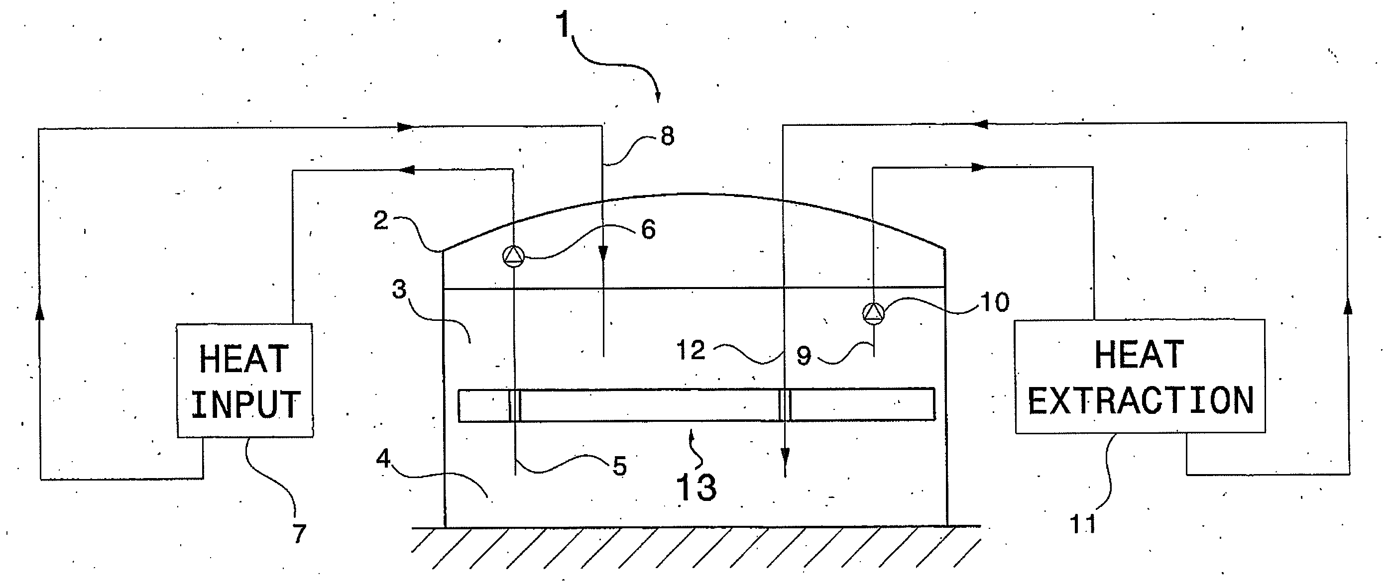
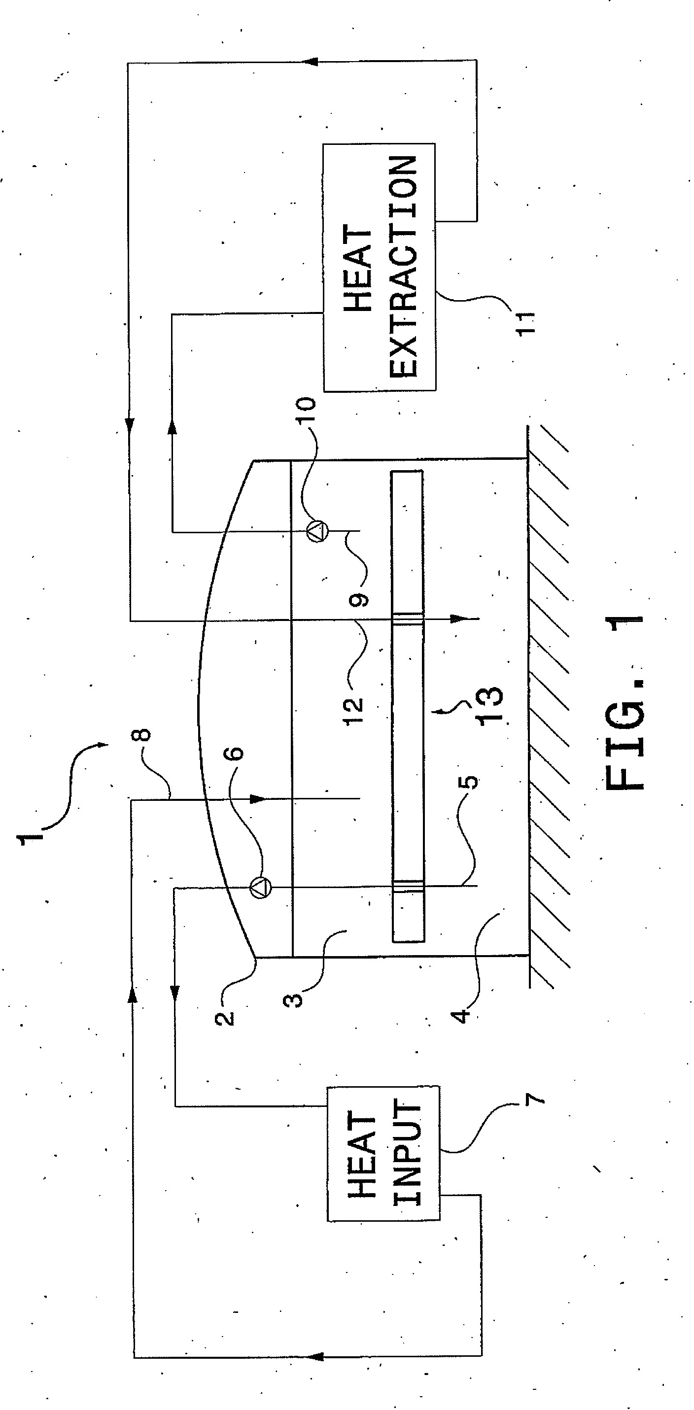
[0062]FIG. 1 shows the schematic arrangement of a thermal storage system (1), which can be the storage system of a solar thermal power plant. The storage system (1) includes a thermocline storage tank (2), which stores two masses of fluid at different temperatures. The mass of colder fluid (4) is normally denser than the mass of hotter fluid (3), and is stored below it. The tank can typically be of the vertical cylindrical type, with a diameter of about 40 m and a height of about 15 m. In many common solar applications, the cold fluid will usually be at a temperature of about 300° C., and the hot fluid will be at a temperature of about 400° C., and the fluid stored at both temperatures will typically be a mixture of molten nitrate salts.

[0063]The barrier member object of the present invention, represented schematically in in FIG. 1 and designated by numeral (13), is located in the interface between the hot and cold fluids, physically separating and insulating them, so that the heat ...


PUM


Abstract

A thermocline storage tank is presented, which includes a barrier member that floats between the two fluids stored at different temperatures, physically separating and insulating them. The floating barrier includes a number of design features that broaden its application scope, enabling it for use in fields like thermal storage systems of solar power plants.

Description

TECHNICAL FIELD OF THE INVENTION[0001]The present invention generally relates to the field of thermal energy storage systems, and more particularly to the improvements in the design of thermocline storage tanks.BACKGROUND OF THE INVENTION[0002]Thermal energy storage systems are generally used in applications where it is necessary to decouple energy collection from energy delivery. Solar energy collection systems are a typical example of this, as there may normally exist a demand for energy during periods without solar radiation, when no energy can be collected, but energy has still to be delivered to satisfy said demand.[0003]The size of solar energy collection systems may range from small domestic collector systems, used for heating water, to much larger collector systems, as those encountered in solar electric power plants.[0004]One way of storing thermal energy consists of employing the sensible heat of a fluid. During periods with solar radiation, thermal energy is stored by hea...

Claims


Application Information

Patent Timeline
IPC IPC(8): F24H7/00
CPCF24D11/00F24D2200/14F28D20/0039F28D2020/0095Y02E60/142Y02E70/30F28D2020/0047Y02B10/20Y02E60/14
Inventor LATAPEREZ, JES S M.BLANCO LORENZO, JULIO
Owner SENER ING Y SISTEMAS
Why Eureka
Try Eureka