
Ultrasonic inspection method and ultrasonic inspection device

an ultrasonic inspection and ultrasonic technology, applied in the direction of liquid/fluent solid measurement, machines/engines, instruments, etc., can solve the problems of not being able to identify a shape echo and a defect echo, and being unable to confirm the correlation between the three-dimensional inspection data and the three-dimensional shape data, etc., to achieve the effect of quick identification of a shape echo

Active Publication Date: 2011-07-07
HITACHI-GE NUCLEAR ENERGY LTD
View PDF4 Cites 16 Cited by
  • Summary
  • Abstract
  • Description
  • Claims
  • Application Information

AI Technical Summary

Benefits of technology

An object of the present invention is to provide an ultrasonic inspection method and an ultrasonic inspection device, which allow position adjustment of three-dimensional inspection data and three-dimensional shape data to be appropriately performed on a display screen, thereby allowing identification of a defect echo and a shape echo quickly performed even when information on the relative positions of a probe and an object to be inspected is not provided.
In the ultrasonic inspection method, it is possible to perform position adjustment of the three-dimensional inspection data and the three-dimensional shape data even when information on the relative positions of the probe and the object to be inspected is not provided, thereby making it possible to quickly identify a shape echo and a defect echo.
In the ultrasonic inspection device, it is possible to perform position adjustment of the three-dimensional inspection data and the three-dimensional shape data even when information on the relative positions of the probe and the object to be inspected is not provided, thereby making it possible to quickly identify a shape echo and a defect echo.
The present invention allows position adjustment of three-dimensional inspection data and three-dimensional shape data even when information on the relative positions of a probe and an object to be inspected is not provided, thereby making it possible to quickly identify a shape echo and a defect echo.

Problems solved by technology

If the correction is not appropriately performed, it is not possible to confirm the correlation between the three-dimensional inspection data and the three-dimensional shape data.
Thus, it is not possible to identify a shape echo and a defect echo.
This operation is repeatedly performed until identification of a shape echo and a defect echo can be attained; it disadvantageously takes much time to identify the echoes.
Especially in a case where the numerical information on the relative positions of the probe and the object to be inspected is not provided, a problem arises that is how to adjust the positions of the probe and the object to be inspected.
In recent years, a problem arose that is about countermeasures to be taken against light water reactors that are in a operating condition for a long passage of time in Japan.
Thus, it is difficult to inspect the welded part from the inside of the pressure container.
However, it is not possible to detect, with millimeter accuracy, the position of the probe relative to the position of the welded part located inside the large pressure container.

Method used


Image

  • Ultrasonic inspection method and ultrasonic inspection device
  • Ultrasonic inspection method and ultrasonic inspection device
  • Ultrasonic inspection method and ultrasonic inspection device

Examples


first embodiment

The configuration and operations of an ultrasonic inspection device according to the present invention are described below with reference to FIGS. 1 to 9.

First, the entire configuration of the ultrasonic inspection device according to the first embodiment is described with reference to FIGS. 1 to 6.

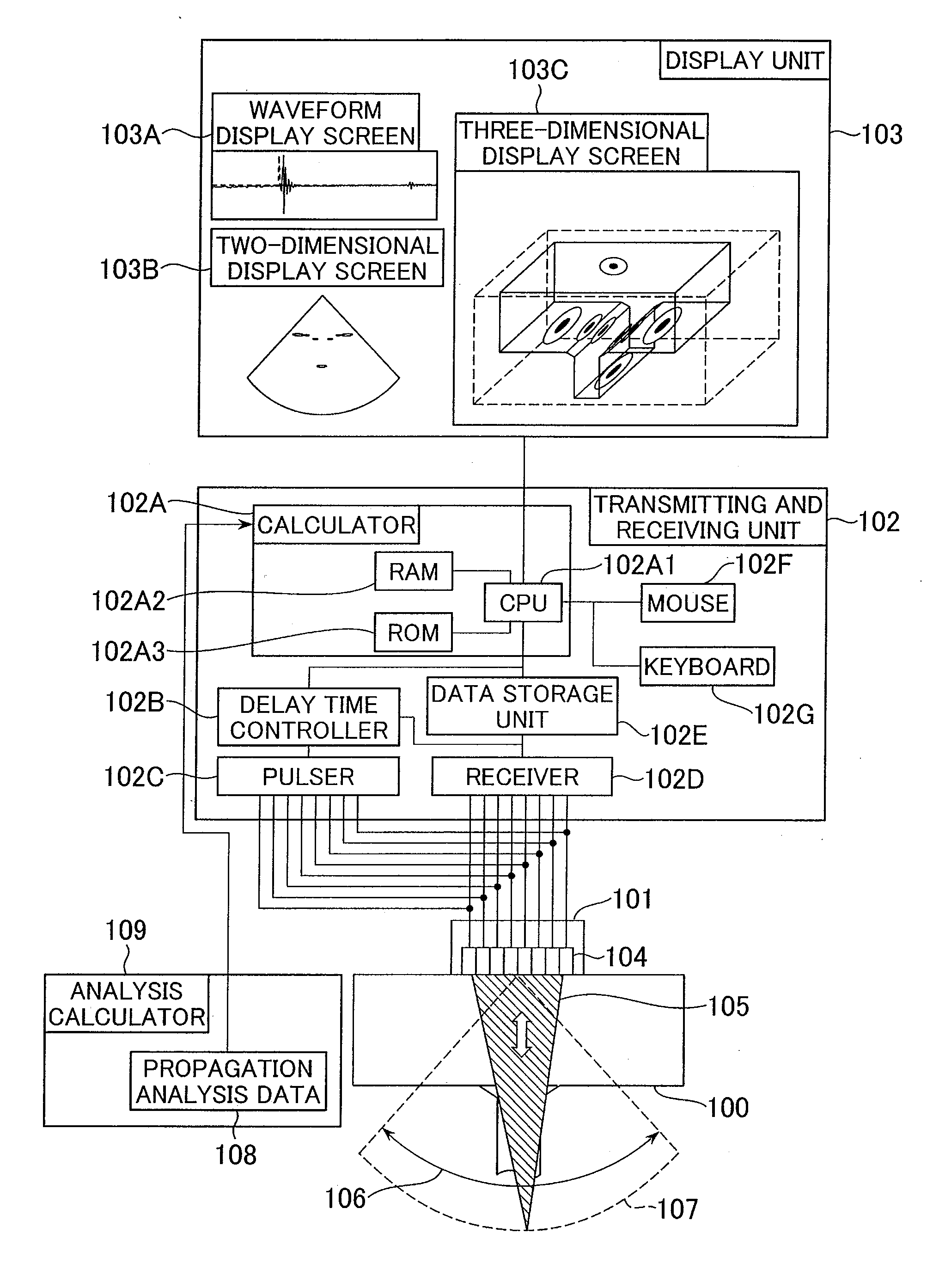
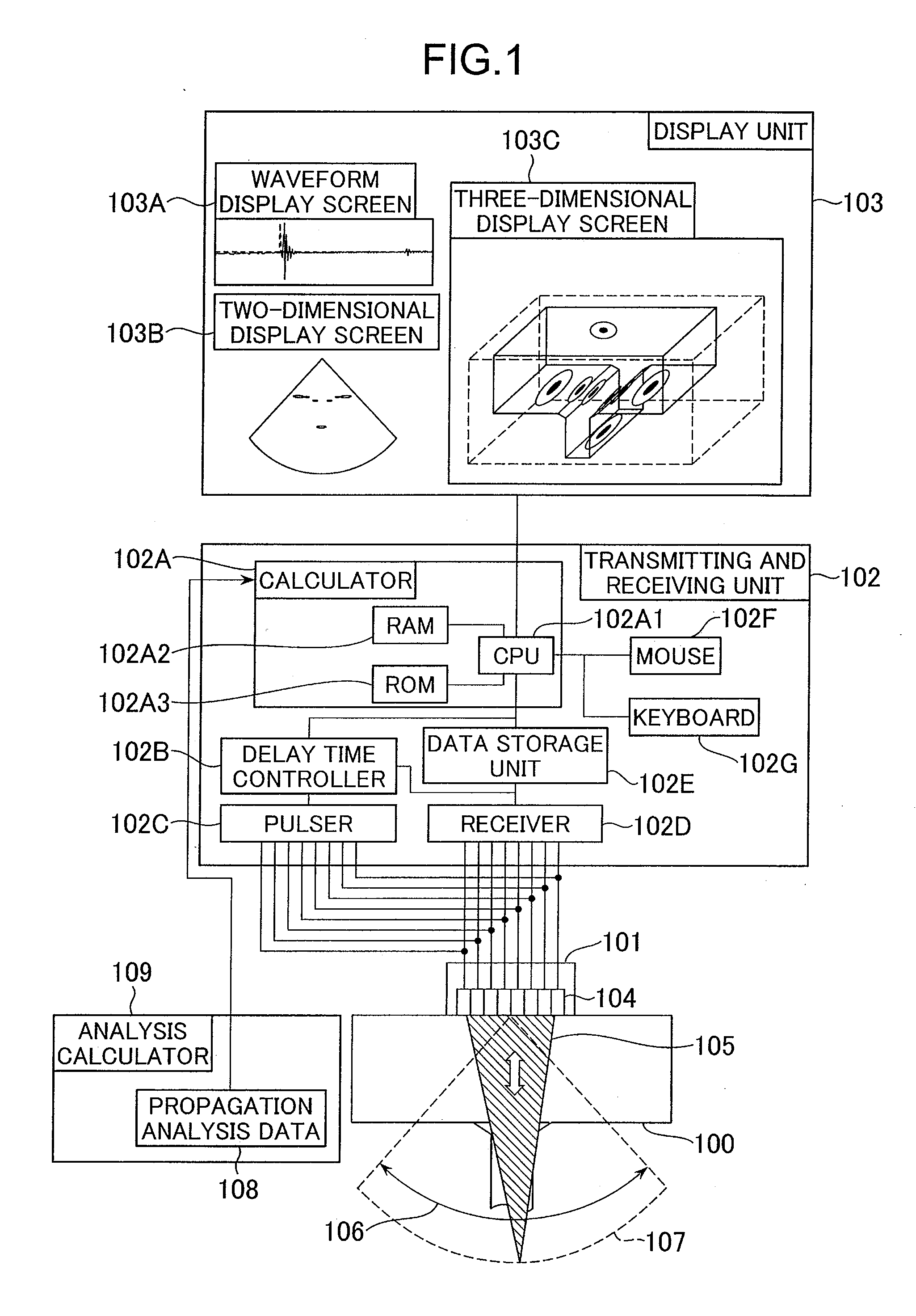
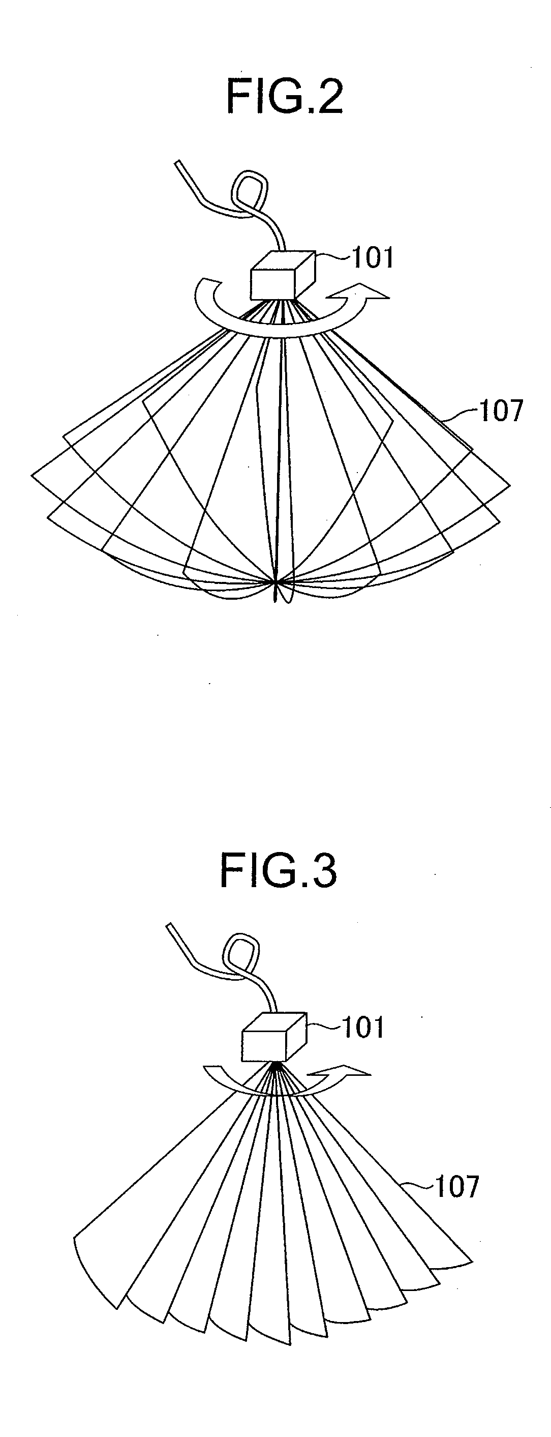
FIG. 1 is a diagram showing the entire configuration of the ultrasonic inspection device according to the first embodiment. FIGS. 2 and 3 are diagrams each showing a scanning method in which the ultrasonic inspection device according to the first embodiment acquires three-dimensional inspection data. FIG. 4 is a diagram showing an example of display of the three-dimensional inspection data in the ultrasonic inspection device according to the first embodiment. FIGS. 5 and 6 are diagrams each showing an example of display of the three-dimensional inspection data and three-dimensional shape data in the ultrasonic inspection device according to the first embodiment.

The ultrasonic inspection d...

second embodiment

FIG. 10 is a diagram showing an example of display of two-dimensional inspection data and three-dimensional shape data in the ultrasonic inspection device according to the

The first embodiment describes the example of the position adjustment of the three-dimensional inspection data 401 and the three-dimensional shape data 501. On the other hand, the second embodiment describes an example of position adjustment of the two-dimensional inspection data and the three-dimensional shape data 501 that are acquired by a linear scanning method or a sector scanning method.

As a configuration of the ultrasonic inspection device and an automatic positioning method according to the second embodiment are the same as those according to the first embodiment, a description thereof is omitted. However, since the two-dimensional inspection data is output as image data of a pixel format or the like, a method for displaying results obtained after the position adjustment is different from that according to ...

third embodiment

FIG. 11 is a diagram showing an example of display of two-dimensional inspection data and cross sectional position of three-dimensional shape data in the ultrasonic inspection device according to the

FIG. 11 shows the state in which a planar image of the sector 107 displayed as the two-dimensional inspection data and the three-dimensional shape data 501 are two-dimensionally displayed on the two-dimensional display screen 103B. The three-dimensional shape data 501 is displayed on the screen only an outline thereof in form of cross sectional view of a section to which the two-dimensional inspection data corresponds. Thus, the relationship between the cross section and the shape corresponding to the cross section can be easily recognized. The displaying of the outline of the cross sectional image of the three-dimensional shape data can be easily achieved by calculating lines of intersections of triangles constituting the STL data (three-dimensional shape data) and the cross-sectional p...


PUM


Abstract

An ultrasonic inspection method and an ultrasonic inspection device allow three-dimensional inspection data and three-dimensional shape data to be appropriately positioned on a display screen and allow a defect echo and a shape echo to be quickly identified even when information on the relative positions of a probe and an object to be inspected is not provided. The ultrasonic inspection data that is generated from the waveforms of ultrasonic waves received by an ultrasonic probe is compared with a plurality of ultrasonic propagation data pieces calculated by a ray tracing method on the basis of the three-dimensional shape data on an object to be inspected. The position of the three-dimensional inspection data or the three-dimensional shape data is moved relative to the other data position on the basis of the comparison results, thereby displaying the three-dimensional inspection data and the three-dimensional shape data while overlapping each other.

Description

BACKGROUND OF THE INVENTION1. Field of the InventionThe present invention relates to an ultrasonic inspection method and an ultrasonic inspection device. The invention more particularly relates to an ultrasonic inspection method in which an array type ultrasonic probe is used, and an ultrasonic inspection device that includes an array type ultrasonic probe.2. Description of the Related ArtIn recent years, constructional materials and the like are inspected by an ultrasonic inspection method. Such a method having being developed more accurately generates an image inside of an object to be inspected in a short time to inspect the inside of the object, as typified by a phased array method and an aperture synthesis method (refer to, for example, Non-Patent Document 1 (Digital signal processing series, volume 12, “Digital signal processing with measurement sensor” pp 143-186, issued by Shokodo, written by Michimasa Kondo, Yukimasa Ohashi, and Akio Jitsumori)).The phased array method is b...

Claims


Application Information

Patent Timeline
IPC IPC(8): G06F19/00
CPCG01N29/0663G01N2291/105G01N29/4409G01N29/262
Inventor KITAZAWA, SOKONO, NAOYUKIBABA, ATSUSHI
Owner HITACHI-GE NUCLEAR ENERGY LTD
Learn More