Steering-force transmitting apparatus for vehicle

a transmission apparatus and steering force technology, applied in the direction of steering control, vehicle components, power driven steering, etc., can solve the problems that the steering-force transmission apparatus equipped with the rotation transmission mechanism has difficulty in being installed on the vehicle, and achieve the effect of increasing the practicability of the steering-force transmission apparatus, reducing the length and high practicability

Inactive Publication Date: 2011-07-07
TOYOTA JIDOSHA KK +1
View PDF4 Cites 3 Cited by
  • Summary
  • Abstract
  • Description
  • Claims
  • Application Information

AI Technical Summary

Benefits of technology

[0006]In the steering-force transmitting apparatus according to the invention, an axially end portion of the main body portion of one of the operating-member-side shaft and turning-device-side shaft and an axially end portion of the other of the operating-member-side shaft and turning-device-side shaft overlap with each other in the above-described axial direction. This arrangement enables the apparatus to have a small length as measured in the axial direction, thereby making it possible to facilitate installation of the apparatus onto the vehicle, namely, to improve installability of the apparatus onto the vehicle. Owing to such a technical advantage, the present invention is effective to improve practicability of the steering-force transmitting apparatus provided with the rotation transmitting mechanism.(B) Modes of the Invention
[0060]The rotation of the operating-member-side shaft is transmitted to the turning-device-side shaft via the axially protruding portion. The axially protruding portion receives a relatively large load that is applied thereto by rotation of the operating-member-side shaft. In the steering-force transmitting apparatus according to this mode (15), the pin included in the axially protruding portion is fixedly fitted in the hole that is provided in the radially extending portion. For reliably maintaining fixation of the pin in the hole in spite of the large load applied to the axially protruding portion, it is preferable that the fitted portion of the pin has a large axial length. In the above-described arrangement in which the annular-shaped flange portion as the radially extending portion is rotatably supported by the housing, it is possible to reduce an area of a portion of the outer circumferential surface of the first main body portion, which portion is required for provision of the bearings. The radially extending portion can have an axial length that is increased by an amount corresponding to the reduction of the area of the required portion of the outer circumferential surface of the first main body portion, whereby the axial length of the fitted portion of the pin can be increased. Therefore, the technical advantage provided by the above-described arrangement in which the annular-shaped flange portion as the radially extending portion is rotatably supported by the housing, is enjoyable particularly in the apparatus according to this mode (15).

Problems solved by technology

Therefore, the steering-force transmitting apparatus equipped with the rotation transmitting mechanism has difficulty in being installed onto a vehicle, since it requires an installation space having a larger length as measured in a longitudinal direction of the vehicle, as compared with the steering-force transmitting apparatus not equipped with the rotation transmitting mechanism.
Thus, the steering-force transmitting apparatus provided with the rotation transmitting mechanism is still in a developing stage with various problems such as the above-described installation difficulty, and there is still room for improvements.

Method used


Image

  • Steering-force transmitting apparatus for vehicle
  • Steering-force transmitting apparatus for vehicle
  • Steering-force transmitting apparatus for vehicle

Examples


first embodiment

1. Overall Construction of Steering System

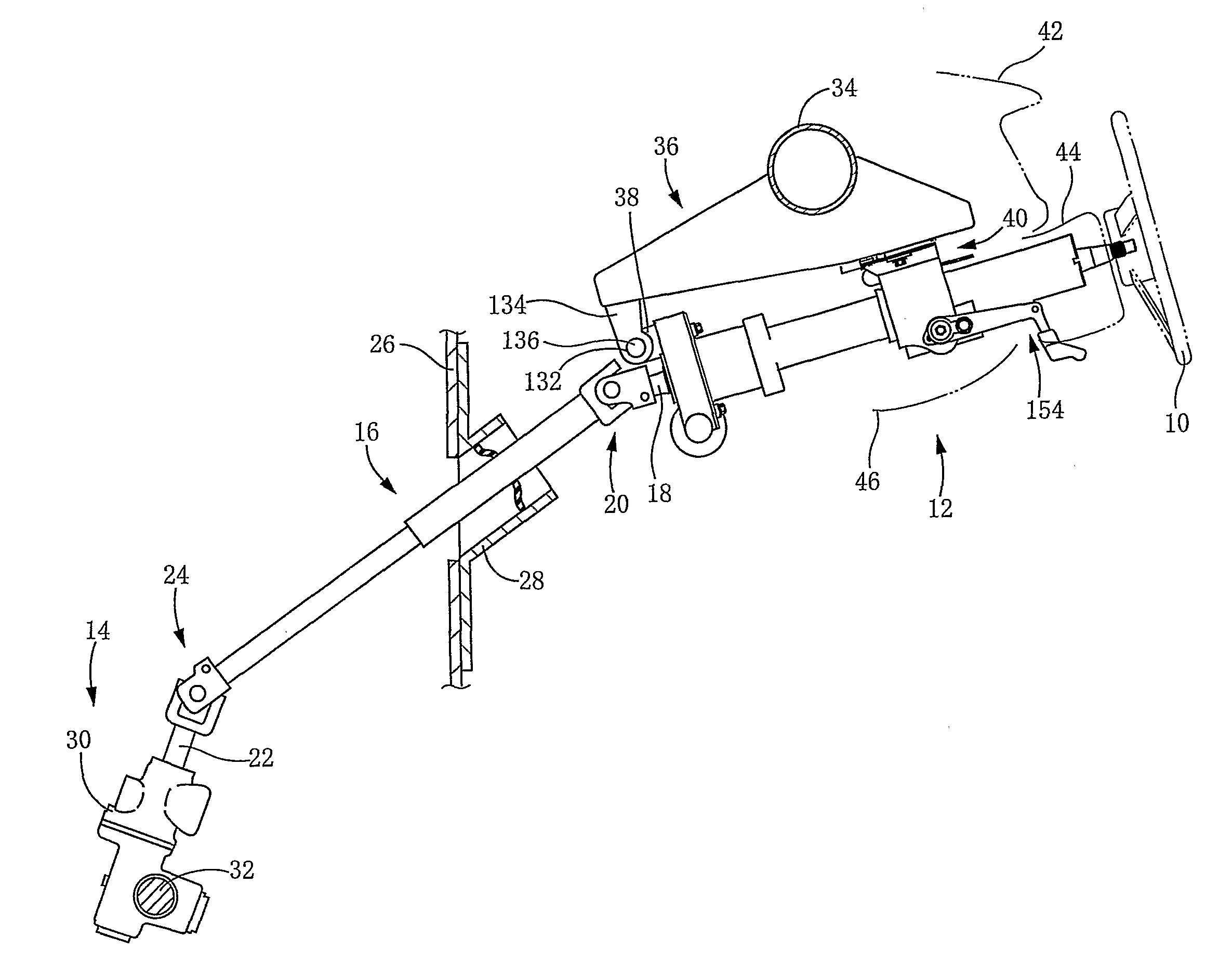
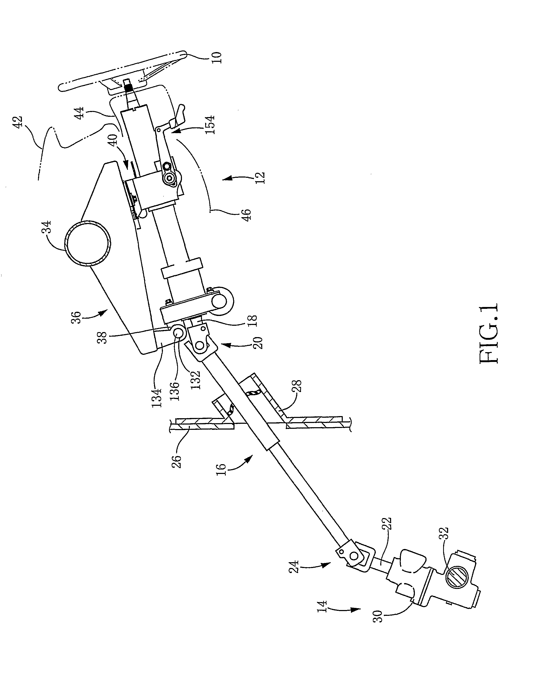
[0076]FIG. 1 shows an overall construction of a vehicle steering system that is to be installed on a vehicle. The vehicle steering system is provided with a steering-force transmitting apparatus that is constructed according to a first embodiment of the invention. The present steering system includes: a steering wheel 10 as a steering operation member operable by an operator of the vehicle; a steering-force transmitting apparatus 12; a wheel turning device 14 configured to turn wheels of the vehicle; and an intermediate shaft 16 that is disposed between the steering-force transmitting apparatus 12 and the wheel turning device 14. The steering wheel 10 is held by an axial end portion of the steering-force transmitting apparatus 12. A universal joint 20 is provided to interconnect an axial end portion of the intermediate shaft 16 and an output shaft 18 that is included in the steering-force transmitting apparatus 12. Meanwhile, another univers...

second embodiment

[0107]There will be described a steering-force transmitting apparatus 200 that is constructed according to a second embodiment of the invention. The present steering-force transmitting apparatus 200 is provided with an EPS section 202 which is different in construction from the EPS section 52 provided in the above-described apparatus 12 constructed according to the first embodiment. The EPS section 202 has an EPS housing 204 in which the output shaft 18 is rotatably supported at their portions that are different from those in the above-described EPS housing 84 of the EPS section 52. Except for this different part of the EPS section, the steering-force transmitting apparatus 200 is substantially the same as the above-described apparatus 12. In the following description as to the apparatus 200 of this second embodiment, the same reference signs as used in the above-described apparatus 12 will be used to identify the functionally corresponding elements, and redundant description of the...

third embodiment

[0111]It is preferable that the torsion bar included in the output shaft is as long as possible in view of its required stiffness. However, where the required stiffness can be obtained even with reduction of the axial length of the torsion bar, the axial length of the output shaft can be reduced by the reduction of the axial length of the torsion bar. Further, the entire axial length of the steering-force transmitting apparatus can be reduced by the reduction of the axial length of the output shaft. It is preferable to reduce the entire axial length of the steering-force transmitting apparatus in view of a limited space available for installation of the apparatus onto the vehicle. In the steering-force transmitting apparatus 12 of the first embodiment shown in view (a) of FIG. 12, the bearings 100, 102, rotational angle sensor 108 and worm wheel 106 are arranged with little clearance therebetween in a portion of the outer circumferential surface of the output shaft 18, which portion...


PUM


Abstract

A steering-force transmitting apparatus including (a) an operating-member-side shaft; (b) a turning-device-side shaft offset from the operating-member-side shaft; and (c) a rotation transmitting mechanism having (c-1) an axially protruding portion provided in one of the two shafts and (c-2) a radially extending groove provided in the other of the two shafts such that the axially protruding portion is engaged in the radially extending groove. The rotation transmitting mechanism is configured to change a rotational phase difference between the two shafts while causing one of the two shafts to be rotated by rotation of the other of the two shafts. An axially end portion of a main body portion of one of the two shafts and an axially end portion of the other of the two shafts overlap with each other in the axial direction.

Description

[0001]This application is based on Japanese Patent Applications No. 2008-254781 and No. 2008-254782 filed on Sep. 30, 2008, the content of which is incorporated hereinto by reference.TECHNICAL FIELD[0002]The present invention relates to a steering-force transmitting apparatus for a vehicle, which is configured to transmit a steering force that is applied to a steering operation member of a vehicle, to a wheel turning device of the vehicle.BACKGROUND ART[0003]In recent years, there is a development of a steering-force transmitting apparatus for a vehicle having (i) a steering operation member operable by an operator of the vehicle and (ii) a wheel turning device configured to turn a wheel of the vehicle. The steering-force transmitting apparatus includes an operating-member-side shaft that is connected at its axial end portion to the steering operation member, a turning-device-side shaft that is connected at its axial end portion to the wheel turning device, and a rotation transmitti...

Claims


Application Information

Patent Timeline
IPC IPC(8): B62D1/19B62D1/16
CPCB62D1/16B62D5/0409B62D1/166
Inventor TANAKA, HAJIMEYAMAKAWA, TOMONARI
Owner TOYOTA JIDOSHA KK
Why Eureka
Try Eureka