
Marine seismic source

a seismic source and marine technology, applied in seismology, seismology, instruments, etc., can solve the problems of not being able to generate energy only within a specified frequency range, affecting marine life, and reducing the potential acoustic energy and overall acoustic efficiency of the devi

Active Publication Date: 2011-07-07
BP CORP NORTH AMERICA INC
View PDF13 Cites 70 Cited by
  • Summary
  • Abstract
  • Description
  • Claims
  • Application Information

AI Technical Summary

Benefits of technology

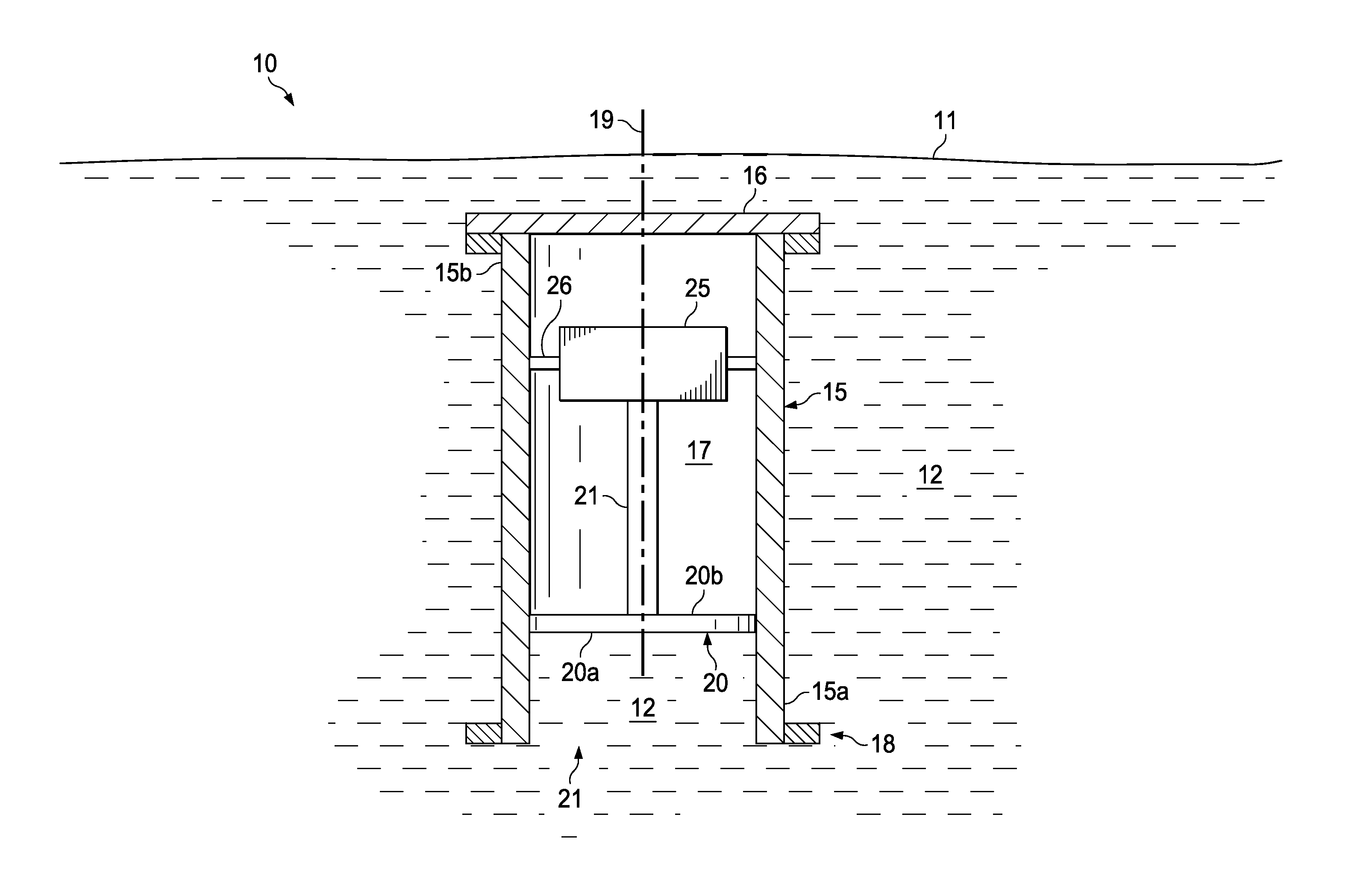
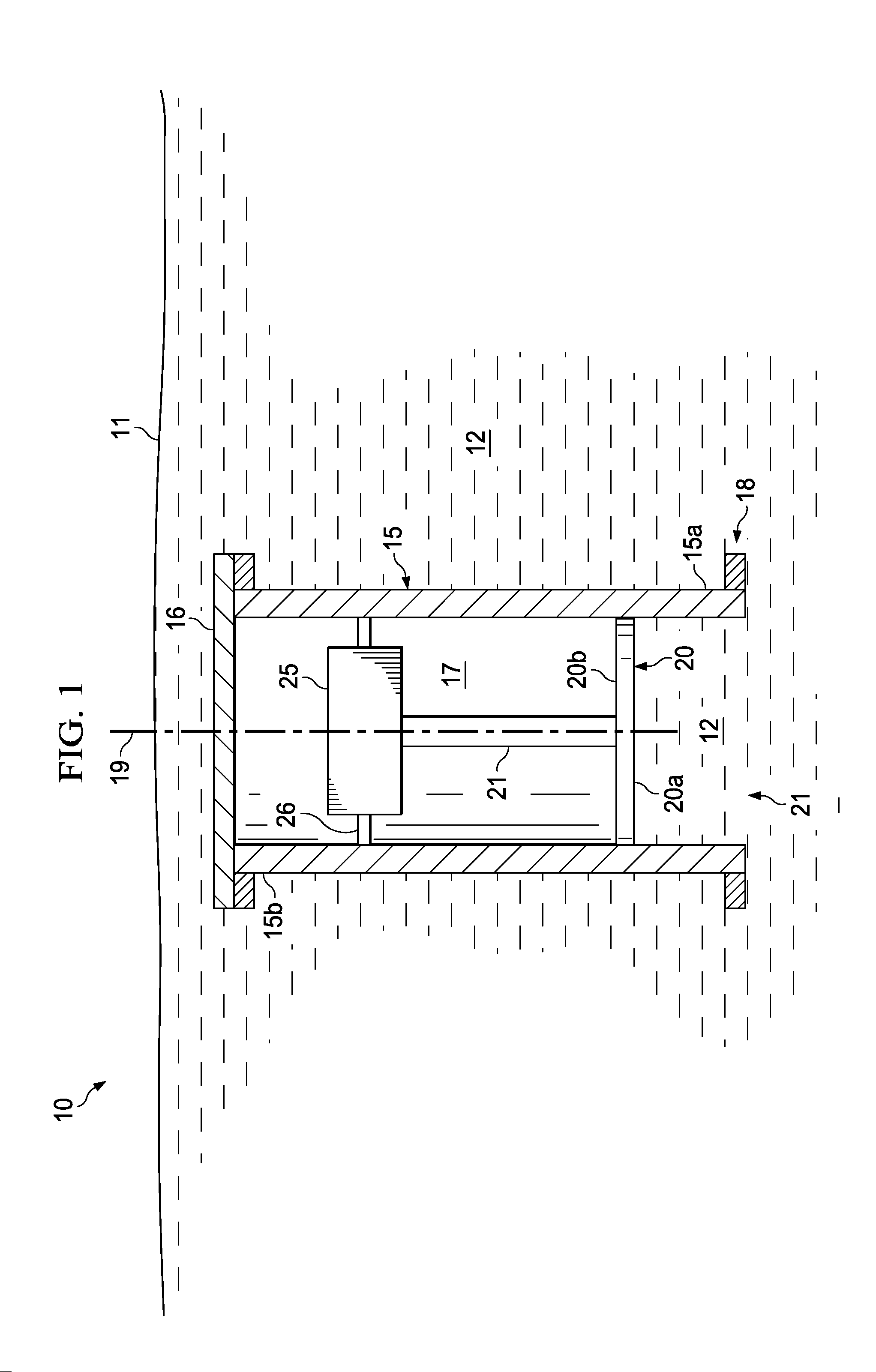
The patent describes a marine seismic source that addresses various shortcomings associated with prior devices. The source has a cylindrical housing with an open end and a closed end, and a piston that can move back and forth inside the housing. The piston has a radially outer surface that increases in size as it moves, which helps to improve the quality of the seismic data. The system also includes a seismic vessel and an oscillating piston seismic source, which can be used for offshore seismic exploration. The technical effects of this invention include improved data quality, improved efficiency, and improved reliability.

Problems solved by technology

Faults and boundaries between different formations and rock types create differences in acoustic impedance that cause partial reflections of the seismic waves.
Some of these approaches provide for strong acoustic waves, but may be harmful to marine life and / or be incapable of generating energy only within a specified frequency range of interest.
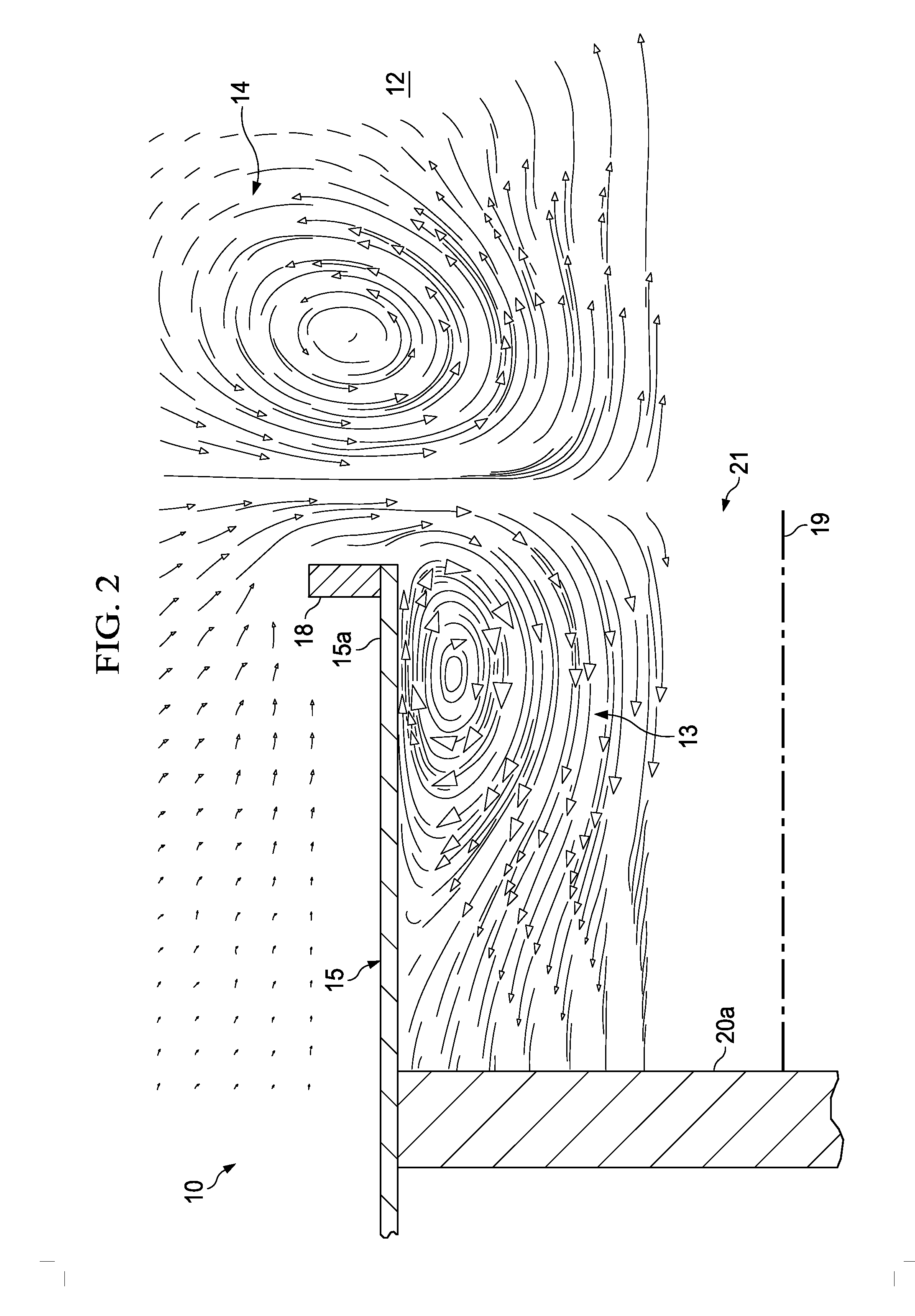
Such turbulence and associated vortices undesirably cause a portion of the energy generated by the piston 20 and transferred into the water 12 to be dissipated uselessly into heat, thereby reducing the potential acoustic energy and the overall acoustic efficiency of the device 10.
At higher frequencies and shallow water depths, another serious problem can happen with an oscillating-piston seismic source—cavitation.
The vacuum then collapses violently, possibly damaging the piston face in the process.
Still further, the abrupt collapse produces turbulence, which dissipates energy uselessly as heat instead of as acoustic radiation.
Such sources would be particularly well received if they can produce energy at frequencies lower than about 8 Hz, which has proven to be difficult to achieve to date using conventional air guns.

Method used


Image

  • Marine seismic source
  • Marine seismic source
  • Marine seismic source

Examples


Embodiment Construction

[0027]The following discussion is directed to various embodiments of the invention. Although one or more of these embodiments may be preferred, the embodiments disclosed should not be interpreted, or otherwise used, as limiting the scope of the disclosure, including the claims. In addition, one skilled in the art will understand that the following description has broad application, and the discussion of any embodiment is meant only to be exemplary of that embodiment, and not intended to intimate that the scope of the disclosure, including the claims, is limited to that embodiment.

[0028]Certain terms are used throughout the following description and claims to refer to particular features or components. As one skilled in the art will appreciate, different persons may refer to the same feature or component by different names. This document does not intend to distinguish between components or features that differ in name but not function. The drawing figures are not necessarily to scale...


PUM


Abstract

A marine seismic source comprises a housing having a central axis, an open end, and a closed end opposite the open end. In addition, the seismic source includes a piston extending coaxially through the open end of the housing. The piston is adapted to axially reciprocate relative to the housing. Further, the piston has a first end distal the housing and a second end disposed within the housing.

Description

CROSS-REFERENCE TO RELATED APPLICATIONS[0001]This application claims benefit of U.S. provisional patent application Ser. No. 61 / 290,611 filed Dec. 29, 2009, and entitled “Marine Seismic Source,” which is hereby incorporated herein by reference in its entirety for all purposes.STATEMENT REGARDING FEDERALLY SPONSORED RESEARCH OR DEVELOPMENT[0002]Not applicable.BACKGROUND[0003]1. Field of the Invention[0004]The invention relates generally to seismic prospecting. More particularly, the invention relates to marine seismic sources for generating seismic waves.[0005]2. Background of the Technology[0006]Scientists and engineers employ seismic surveys for exploration, archeological studies, and engineering projects. In general, a seismic survey is an attempt to map the subsurface of the earth to identify formation boundaries, rock types, and the presence or absence of fluid reservoirs. Such information greatly aids searches for water, geothermal reservoirs, and mineral deposits such as hydro...

Claims


Application Information

Patent Timeline
Patent Type & Authority Applications(United States)
IPC IPC(8): G01V1/38
CPCG01V1/135
Inventor HARPER, MARKDELLINGER, JOSEPH A.THOMPSON, MARTINOPENSHAW, GRAHAM
Owner BP CORP NORTH AMERICA INC
Learn More