
Synchro-lock clutch-combination friction and mechanical locking clutch

Active Publication Date: 2011-06-30
BORGWARNER INC
View PDF23 Cites 20 Cited by
  • Summary
  • Abstract
  • Description
  • Claims
  • Application Information

AI Technical Summary

Benefits of technology

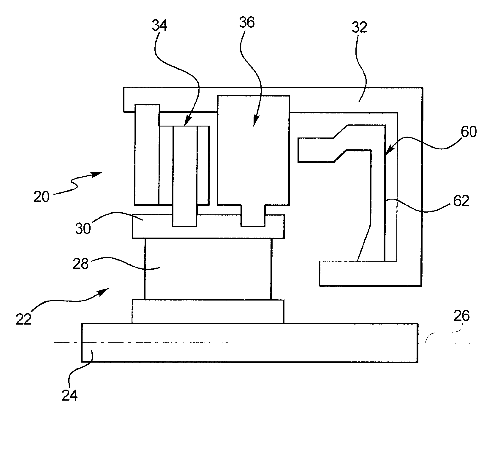
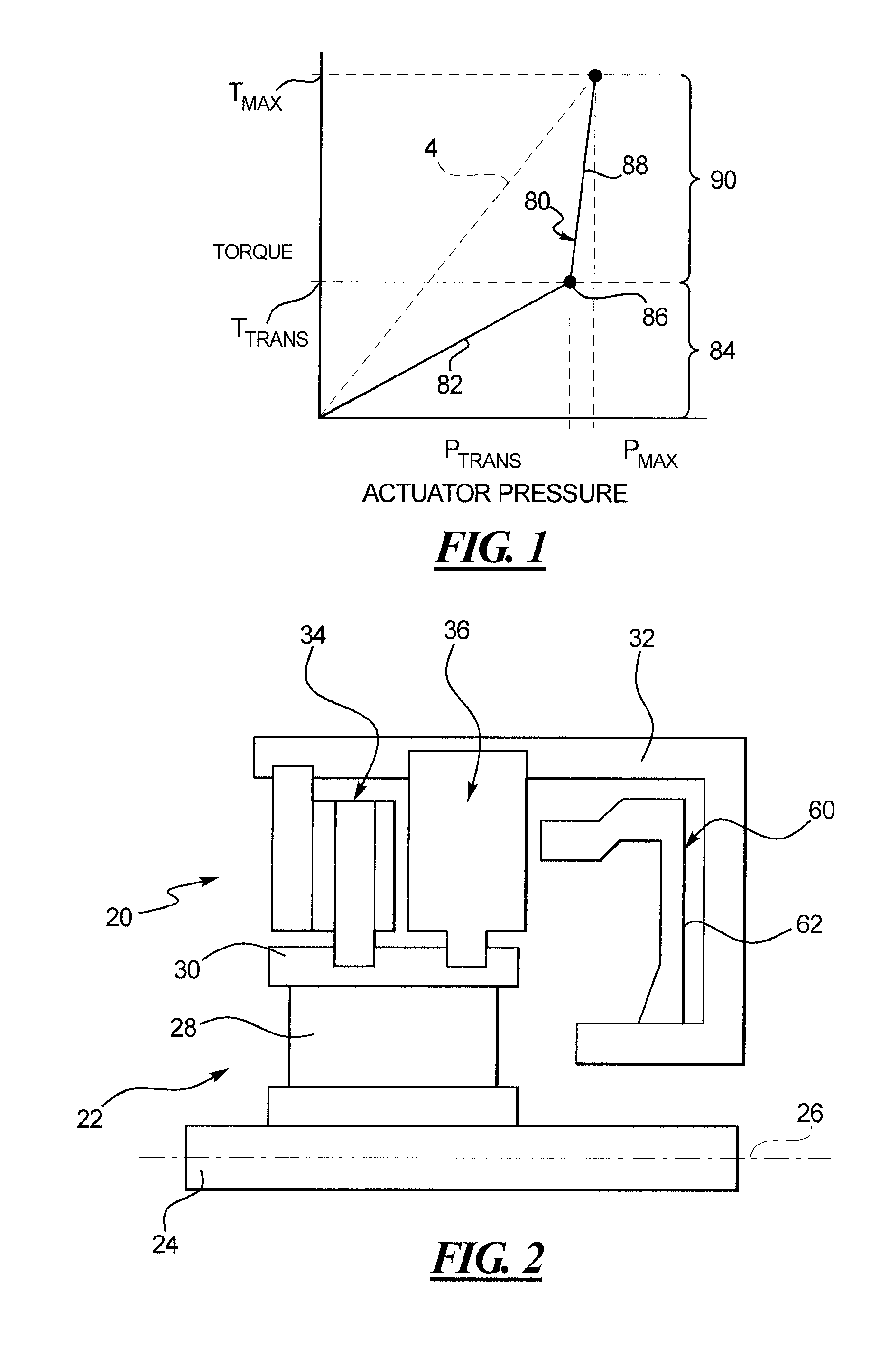
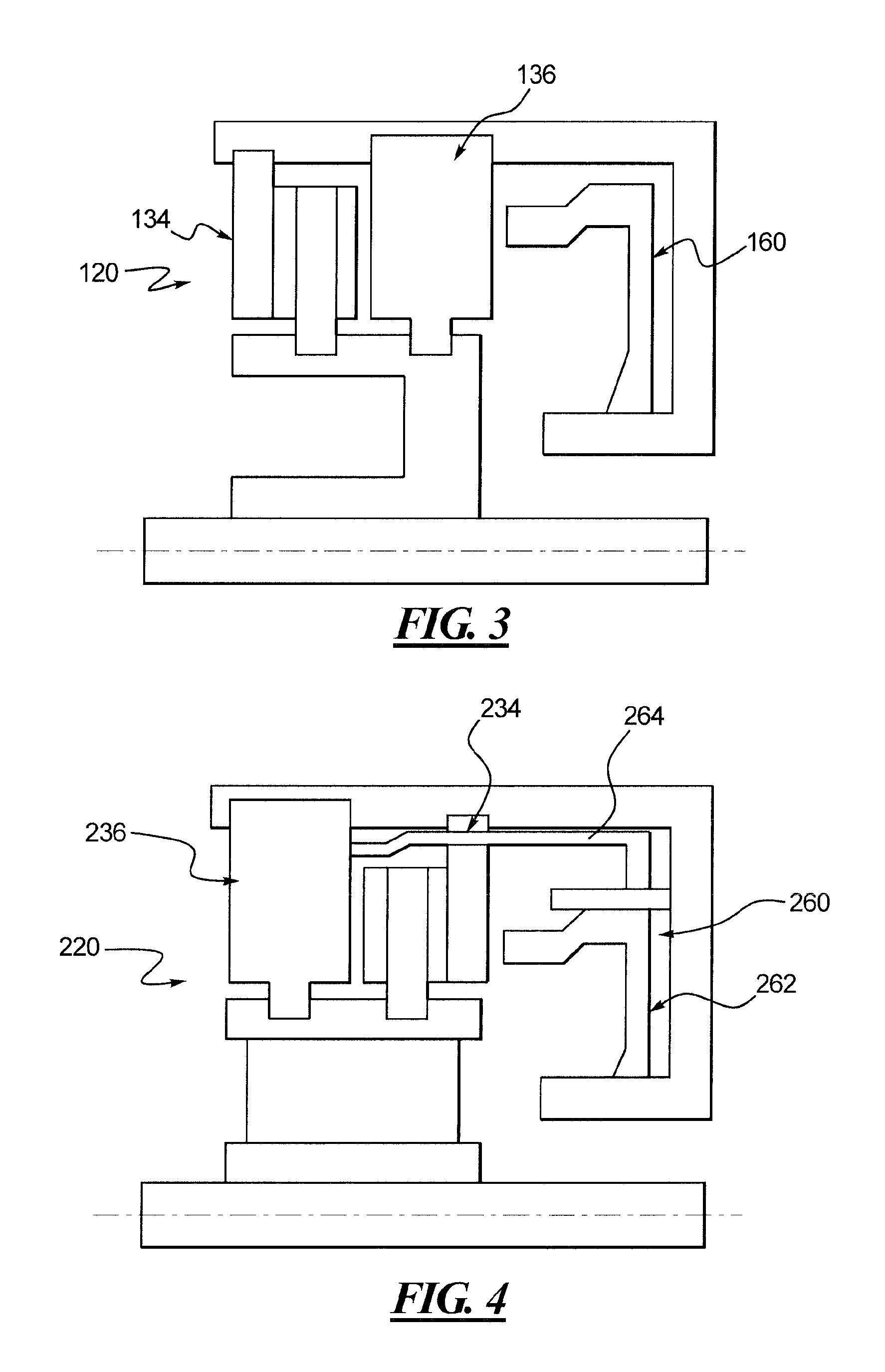
[0009]A clutch control system for transmitting an operational range of torques from a driving member to a driven member is provided having a composite clutch with a friction clutch assembly and a dog clutch assembly. The composite clutch is operable in a friction clutch mode across a first portion of the operational range of torques and a dog clutch mode across a second portion of the opera

Problems solved by technology

When the clutch is unengaged or idling, however, the plates generate a parasitic drag torque due to the viscous shearing action which exists between the drive and driven plates as they rotate at different speeds relative to one another.
This drag torque adversely affects vehicle fuel economy for automatic transmissions, and therefore the use of excessive plates exacerbates this problem.
The use of numerous friction plates also reduces the controllability of the friction clutch in the lower torque range.
The increased sensitivity to actuator pressure exhibited by conventional friction plate clutches makes it more difficult to control the hydraulic valve to obtain the desired torque.
While the friction mechanism transfers some torque, it only begins to rotate the driven shaft so that it is sufficiently synchronized with the driving shaft, and is not intended to operate over any appreciable portion of the operational torque range of the transmission.

Method used


Image

  • Synchro-lock clutch-combination friction and mechanical locking clutch
  • Synchro-lock clutch-combination friction and mechanical locking clutch
  • Synchro-lock clutch-combination friction and mechanical locking clutch

Examples


Embodiment Construction

[0017]A composite clutch is disclosed herein that includes both a friction clutch assembly and a dog clutch assembly. The friction clutch assembly is used to transmit torque from a driving member to a driven member across a first or lower portion of the operational range of torques. The dog clutch assembly is used to transmit torque across a second or upper portion of the operational range of torques. As a result, the composite clutch provides the benefit of good shift feel from the friction clutch assembly with a high static torque capacity of a dog clutch. In addition, the number of plates needed in the friction clutch assembly is minimized, thereby reducing drag torque.

[0018]The composite clutch may be designed and / or controlled to switch from friction clutch mode to dog clutch mode at a desired transition point. The transition point may be selected according to desired operating parameters. Accordingly, output torque is better controlled across the lower portion of the operation...


PUM


Abstract

A composite clutch used to transmit an operational range of torques from a driving member to a driven member includes a friction clutch assembly and a dog clutch assembly. The friction clutch assembly includes a number of first friction clutch members coupled to the driving member and a number of second friction clutch members coupled to the driven member. The number of first friction clutch members and the number of second friction clutch members are selected to transmit torque across a first portion of the operational range of torques. An actuator assembly is operatively coupled to the friction clutch assembly and the dog clutch assembly. The composite clutch may be operated in friction clutch and dog modes to provide improved controllability in lower torque operation.

Description

CROSS-REFERENCE TO RELATED APPLICATION[0001]This is a non-provisional patent application claiming priority under 35 USC 119(e) to U.S. Provisional Patent Application No. 61 / 045,477 filed on Apr. 16, 2008.FIELD OF THE DISCLOSURE[0002]The present disclosure generally relates to torque transmission components, and more particularly relates to clutches used to transmit torque in vehicles.BACKGROUND OF THE DISCLOSURE[0003]Various types of clutches have been used to transmit torque in vehicles. In a vehicle having an automatic transmission, for example, multiple clutches are used to engage or disengage selected gearsets to obtain a desired gear ratio. The clutches provided for this purpose are typically friction plate clutches, which include a plurality of inner or drive plates that are splined to a rotatable hub. A housing or case is coaxially aligned with the hub and supported for rotation independent of the hub. A plurality of outer or driven plates are splined to the housing or case a...

Claims


Application Information

Patent Timeline
IPC IPC(8): F16D47/04F16D11/00F16D13/52
CPCF16D11/14F16D21/00F16D13/38
Inventor VIERK, DAVIDMARCINIAK, JAMES G.KOWAL, STEVENPAPANIA, JAMES R.
Owner BORGWARNER INC
Learn More