
Interlock for swing-out door

Inactive Publication Date: 2011-06-30
GEBR BODE & CO GMBH
View PDF9 Cites 3 Cited by
  • Summary
  • Abstract
  • Description
  • Claims
  • Application Information

AI Technical Summary

Benefits of technology

[0004]The invention provides a secure interlock of a door in the door portal of a vehicle, wherein the closed door is supposed to have a large degree of comfort with regard to noise. For this purpose, the door is supposed to abut against the seal so firmly that no or only little wind noise is generated and the door itself does not produce any noise, for example by rattling, even at higher speeds. Small forces are supposed to be required for closing and the mechanism concerned is supposed to have a simple structure.
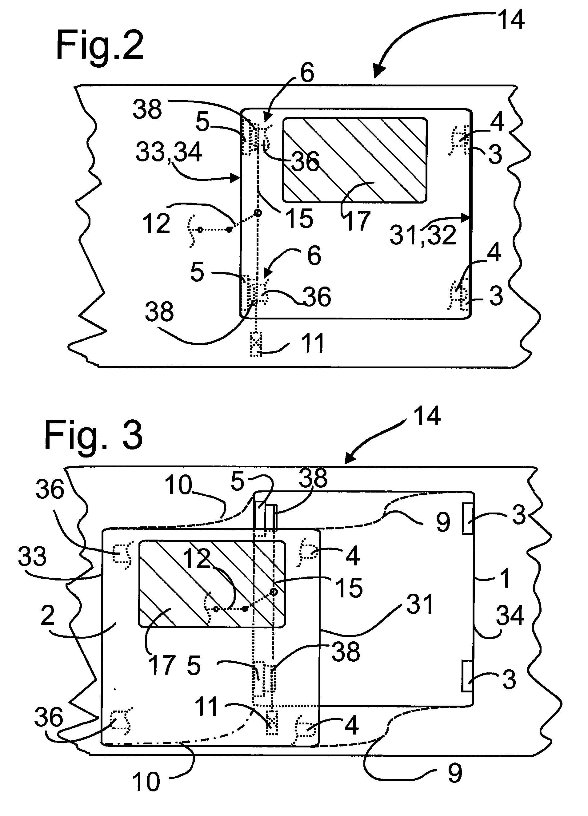
[0005]According to the invention, a generic door system is provided, wherein at least one retention bolt latching into a counter support disposed on the primary portal edge is provided on the primary closing edge, and wherein at least one closure element cooperating with a second closure element disposed on the secondary portal edge and closing the door is disposed on the secondary closing edge. The present invention provides an advantageous interlock that can be actuated by means of the sequence of movements provided by the kinematic system of the door. Preferably, eight interlocking members are allocated to a door in a door portal. This means that two retention bolts are provided on the primary closing edge of the door, and two counter supports are provided on the primary portal edge, and two first closure elements are provided on the secondary closing edge and two second closure elements are provided on the secondary portal edge. The interlocking units secure the door in the door portal in such a way that it is firmly pressed against the door portal and into the seal disposed thereon. The seal thus effectively seals the vehicle even in the case of transverse acceleration and strong wind forces. For reasons of an advantageous load distribution, the interlocking members are disposed in the vicinity of the corners on the vertical edges of the door portal or the door.
[0015]The second closure element can be fixed on a support disposed on the door portal. This support can be an adjustable block, with the term adjustable meaning that the support can be adjusted by being displaced in the door portal using suitable means, such as elongated holes and screws guided by these elongated holes. This is necessary in order to be able to compensate for manufacturing tolerances of the door portal and / or the door. In this way, the closure can be adjusted such that on the one hand, a sufficient compression of the door seal system is ensured, and on the other hand, that the door is not impeded on its trajectory.

Problems solved by technology

This requires a comparatively strong drive because an unfavorable lever arm is effective in particular when the door seal is being compressed.
A pressure loss in hydraulic or pneumatic systems causes a lack of contact force, so that wind noise is generated and, in a worst case scenario, the door can be pushed open during transit by a person leaning against it.
In the case of hydraulic or pneumatic systems, there is the additional problem that the interlock becomes ineffective in the case of pressure loss in the system, and that the door may inadvertently fall open partially or even completely.

Method used


Image

  • Interlock for swing-out door
  • Interlock for swing-out door
  • Interlock for swing-out door

Examples


Embodiment Construction

[0026]FIG. 1 shows a door portal 1 with a door 2 located therein comprising a primary closing edge 31 and a secondary closing edge 33. A first trajectory 9 is shown in dashed lines on the primary closing edge 31, a second trajectory 10 is shown on the secondary closing edge 33. The primary and secondary closing edges 31, 33 are guided along the trajectories 9, 10 during opening and closing. The primary closing edge 31 is located on the door 2 to the front in the closing direction, the secondary closing edge 33 is located on the door 2 to the rear in the closing direction. The primary and secondary closing edges 31, 33 are the vertically extending edges of the door 2. The primary closing edge 31, in the closed position of the door 2, directly abuts against a vertically extending primary portal edge 32, and the secondary closing edge 33 of the door 2 directly abuts against a secondary portal edge 34.

[0027]The door 2 is in the closed position, with the seals 8 abutting against their as...


PUM


Abstract

The invention relates to a door system for a public transit vehicle, comprising a door (2) and a door portal (1), wherein the door (2) is moved substantially parallel to the exterior vehicle wall when the door is opened and closed and wherein the door (2) comprises a vertical math closing edge (31) in front in the direction of closing, said edge abutting a main portal edge (32) running vertically in the door portal (1) in the closed position of the door (2), and a secondary closing edge (33) behind in the direction of closing, said secondary closing edge abutting a secondary portal edge (34) running vertically in the door portal (1) in the closed position of the door (2). The main closing edge (31) moves along an s-shaped path of motion (10) when opening and closing takes place and the secondary closing edge (33) moves along a circular path of motion (10). At least one locking bolt (4) is provided at the main closing edge (31), said locking bolt engaging into a counter support (3) located at the main portal edge (32). At least one first closure element (36) is located at the secondary closure edge (33), said first closure element cooperating with a second closure element (38) located at the secondary portal edge (34) and sealing the door (2).

Description

TECHNICAL FIELD[0001]The invention relates to a door system for a short and long-distance public transport vehicle, comprising a door and a door portal, wherein the door, during opening and closing, is moved substantially parallel to the outer vehicle wall and the door comprises a vertically extending primary closing edge disposed to the front in the closing direction and abutting, in the closed state of the door, against a primary portal edge extending vertically in the door portal, and comprises a secondary closing edge disposed to the rear in the closing direction and abutting, in the closed state of the door, against a secondary portal edge extending vertically in the door portal, wherein the primary closing edge is moved along an s-shaped trajectory and the secondary closing edge is moved along an arc-shaped trajectory during opening and closing.BACKGROUND[0002]In the area of city and intercity buses, outward-swinging doors are known in which the contact force against the door ...

Claims


Application Information

Patent Timeline
IPC IPC(8): B60J5/04E05B65/20E05B85/22
CPCB61D19/008E05B81/00E05B83/363E05B85/22E05D15/10E05Y2800/00E05F7/04E05Y2600/56E05Y2900/51E05Y2600/40E05F7/005
Inventor PELLEGRINI, ANDREAS
Owner GEBR BODE & CO GMBH
Learn More