
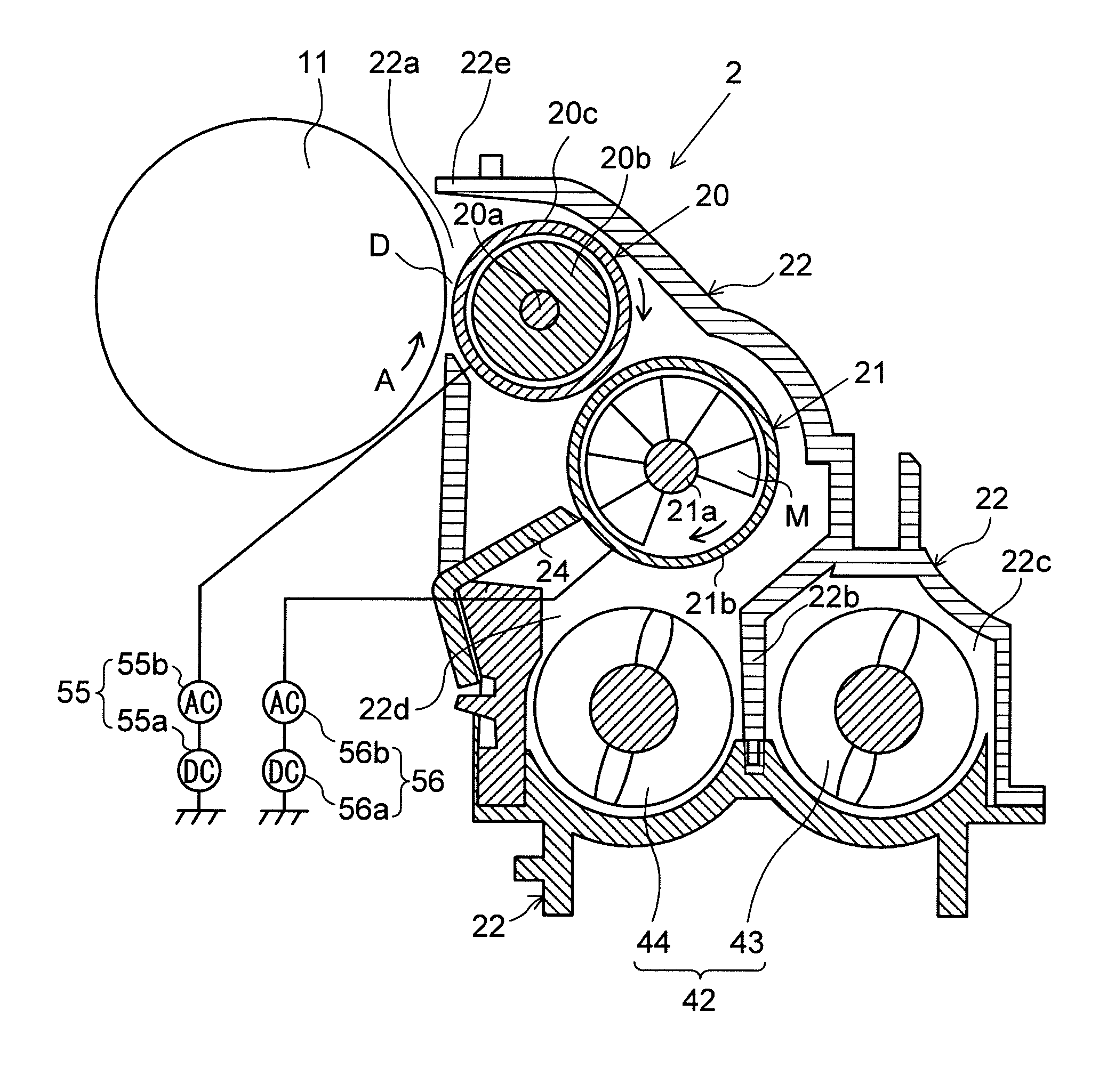
Developing device and image forming apparatus provided therewith

a technology of developing device and image forming apparatus, which is applied in the direction of electrographic process apparatus, instruments, optics, etc., can solve the problems of inability to discharge excessively, unstable developer amount in the developing container, and gradual degradation of charging performance of the carrier with respect to toner, etc., to achieve accurate maintenance and simple structure

Active Publication Date: 2011-06-23
KYOCERA DOCUMENT SOLUTIONS INC
View PDF15 Cites 23 Cited by
  • Summary
  • Abstract
  • Description
  • Claims
  • Application Information

AI Technical Summary

Benefits of technology

[0010]It is therefore an object of the present invention to provide a developing device and an image forming apparatus provided therewith, the developing device having a simple structure with which surplus developer is stably discharged from a developing container and a developer amount in the developing container is accurately maintained to a desired amount.
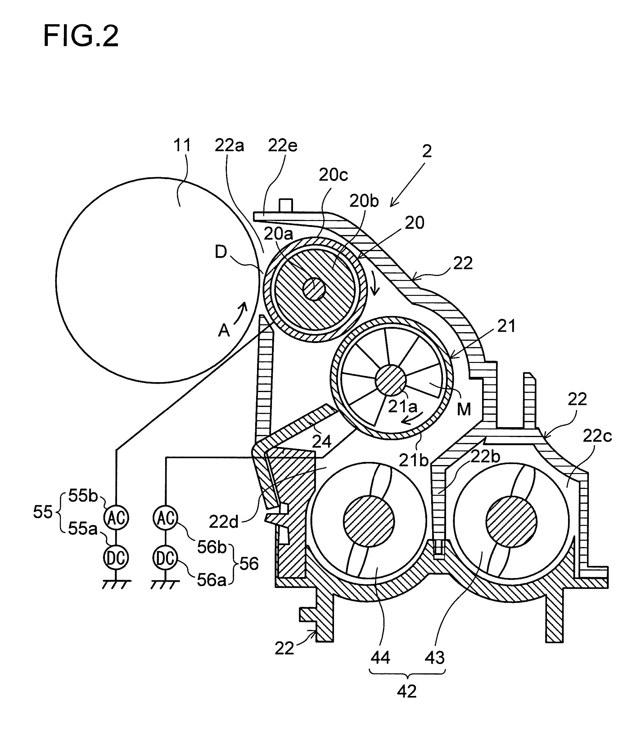
[0011]A developing device according to one aspect of the present invention, includes: a developing roller for supplying developer to an image carrier; a plurality of stirring members each including a helical blade helically extending about a rotary shaft in an axial direction of the rotary shaft, for stirring and conveying the developer supplied to the developing roller; a developing container including a partition portion for partitioning the developing container into conveyance paths in which the developer is circulatingly conveyed by the plurality of stirring members, communication portions for communicating the conveyance paths with each other on both-end-portion sides in a long side direction of the partition portion, a developer replenishing port from which the developer is replenished, and a developer discharge port which is provided on a downstream side of one of the conveyance paths and from which surplus developer is discharged; and a discharge regulating portion provided to one of the plurality of stirring members which is arranged in the one of the conveyance paths, in which the discharge regulating portion includes a regulating member arranged so as to face the developer discharge port, for regulating movement of the developer to the developer discharge port side, and a decelerating conveyance member arranged between the helical blade and the regulating member, for partially reducing a conveying speed of the developer in the one of the conveyance paths.

Problems solved by technology

As a result, charging performance of the carrier with respect to the toner is gradually deteriorated.
However, in the developing device according to the first related art, even when new developer is not replenished, the developer conveyed by the helical blade of each of the stirring members moves to the downstream side of the conveyance path in an undulating manner in conformity with an outer periphery of the helical blade, with the result of colliding against the discharge regulating portion.
As a result, the developer is excessively discharged, which may lead to a risk of instability of the developer amount in the developing container.
In particular, in an apparatus performing high-speed image formation, the stirring members are rotated at high speed together with the photosensitive member, and hence there prominently occurs an inconvenience of excessive discharge of the developer.

Method used


Image

  • Developing device and image forming apparatus provided therewith
  • Developing device and image forming apparatus provided therewith
  • Developing device and image forming apparatus provided therewith

Examples


first embodiment

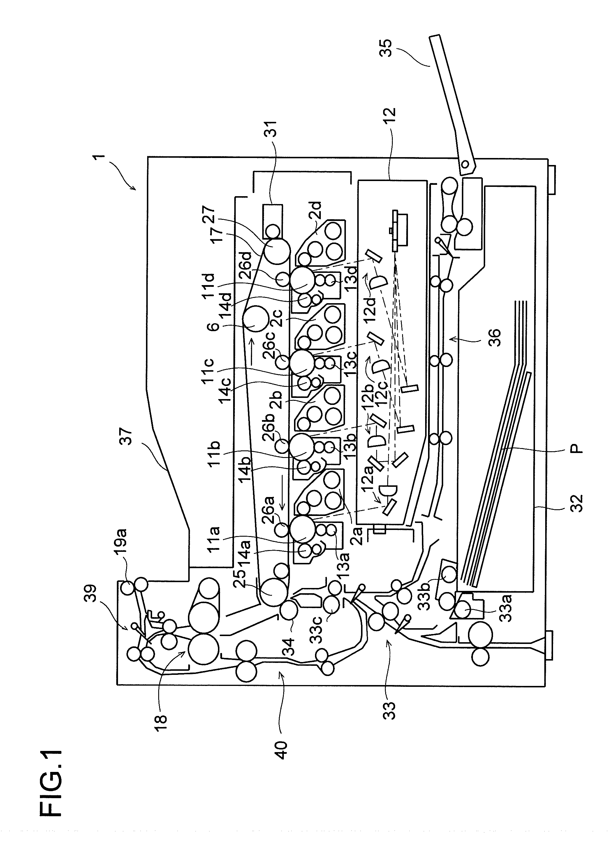
[0035]FIG. 1 is a schematic plan view of a structure of an image forming apparatus including a developing device according to an embodiment of the present invention. An image forming apparatus 1 is a tandem color printer, and has rotatable photosensitive members 11a to 11d for each of which an organic photosensitive member (OPC photosensitive member) is used as a photosensitive material forming a photosensitive layer and which are arranged correspondingly to the following respective colors: black, yellow, cyan, and magenta. Around the photosensitive members 11a to 11d, there are arranged developing devices 2a to 2d, exposure units 12a to 12d, charger 13a to 13d, and cleaning devices 14a to 14d, respectively.

[0036]The developing devices 2a to 2d are arranged respectively on the right of the photosensitive members 11a to 11d so as to face each other, and supply toners to the photosensitive members 11a to 11d. The charger 13a to 13d are arranged respectively on upstream sides of the de...

second embodiment

[0074]FIG. 4 is a sectional side view of a stirring portion of a developing device according to a second embodiment. Description is made mainly of a stirring portion provided with a discharge regulating portion different from that in the first embodiment. Hereinbelow, description of the same parts as those in the first embodiment is omitted.

[0075]The first conveyance path 22c, the second conveyance path 22d, the partition portion 22b, the upstream communication portion 22e, the downstream communication portion 22f, the developer replenishing port 22g, and the developer discharge port 22h of the developing container 22 are arranged and configured similarly to those in the first embodiment. Further, the first stirring member 43 including the rotary shaft 43b and the first helical blade 43a is arranged and configured also similarly to those in the first embodiment. Further, the second helical blade 44a, the discharge blade 53, and a decelerating conveyance member 71 and the regulating ...

third embodiment

[0101]FIG. 10 is a sectional side view of a stirring portion of a developing device according to a third embodiment. Description is made mainly of a stirring portion provided with a discharge regulating portion different from that in the first embodiment.

[0102]The first conveyance path 22c, the second conveyance path 22d, the partition portion 22b, the upstream communication portion 22e, the downstream communication portion 22f, the developer replenishing port 22g, and the developer discharge port 22h of the developing container 22 are arranged and configured similarly to those in the first embodiment. Further, the first stirring member 43 including the rotary shaft 43b and the first helical blade 43a is arranged and configured also similarly to those in the first embodiment. Further, the second helical blade 44a, the discharge blade 53, and a conveying blade 81 and the plate member 82 which constitute a discharge regulating portion are arranged integrally with the rotary shaft 44b ...


PUM


Abstract

Provided is a developing device including: a developing container including a developer replenishing port from which the developer is replenished, and a developer discharge port which is provided on a downstream side of one of the conveyance paths and from which surplus developer is discharged; and a discharge regulating portion provided to one of the plurality of stirring members which is arranged in the one of the conveyance paths, in which the discharge regulating portion includes a regulating member arranged so as to face the developer discharge port, for regulating movement of the developer to the developer discharge port side, and a decelerating conveyance member arranged between the helical blade and the regulating member, for partially reducing a conveying speed of the developer in the one of the conveyance paths.

Description

[0001]This application is based upon and claims the benefit of priority from the corresponding Japanese Patent Application No. 2009-289220 filed on Dec. 21, 2009, Japanese Patent Application No. 2009-289190 filed on Dec. 21, 2009, and Japanese Patent Application No. 2010-039099 filed on Feb. 24, 2010, the entire contents of which are incorporated herein by reference.BACKGROUND OF THE INVENTION[0002]1. Field of the Invention[0003]The present invention relates to a developing device used in an image forming apparatus such as an electrophotographic copier, a printer, a facsimile, and a composite apparatus having functions of those devices, and to an image forming apparatus provided with the developing device. In particular, the present invention relates to a developing device which replenishes a two-component developer including toner and carrier and discharges surplus developer and to an image forming apparatus provided with the developing device.[0004]2. Description of Related Art[00...

Claims


Application Information

Patent Timeline
IPC IPC(8): G03G15/08
CPCG03G15/0839G03G15/0896G03G2215/0822G03G15/0877G03G2215/0833G03G15/0893G03G2215/083G03G15/0844
Inventor WATANABE, AKIHIROHAMAKAWA, HIROYUKIYAMAZAKI, HIROSHI
Owner KYOCERA DOCUMENT SOLUTIONS INC
Learn More