
In-line uninterruptible power supply

a power supply and uninterruptible technology, applied in emergency power supply arrangements, instruments, electric digital data processing, etc., can solve the problem of less than 10% of the reserve power of the battery device expelled as heat, and achieve the effect of reducing cost, weight, and power loss

Inactive Publication Date: 2011-06-23
HERNANDEZ MAURILIO +1
View PDF35 Cites 26 Cited by
  • Summary
  • Abstract
  • Description
  • Claims
  • Application Information

AI Technical Summary

Benefits of technology

[0009]The present invention is generally directed to an in-line uninterruptible power supply for use with an electronic device, wherein the electronic device comprises a base unit and a power adapter. Specifically, the in-line uninterruptible power supply of the various embodiments of the present invention is cooperatively positioned and disposed between the power adapter and the base unit of the electronic device, and is further structured and configured to supply continuous power to the electronic device, even in the event of a temporary power failure. Specifically, the in-line UPS of the present invention uses the power adapter that comes with or is supplied by the electronic device that the user wishes to power. In at least one embodiment, the input and output of the in-line UPS device comprises DC power, eliminating extraneous AC-DC and DC-AC conversions, resulting in a significantly reduced cost, weight, and power loss, and further allowing the in-line UPS to power the electronic device for more than three times longer than traditional UPS devices with comparable or the same battery reserve power.
[0011]Accordingly, although most power sources and wall outlets supply AC power, the signal coming from or otherwise carried by the power adapter of the electronic device, in many applications, is DC power, as the power adapter, in many applications, comprises an AC-DC converter or transformer. Thus, in such an instance, the in-line UPS of the present invention need not comprise an input AC-DC converter. Oftentimes, however, the input signal or voltage coming from the power adapter may need to be raised or lowered so as to correspond with a predetermined battery input signal. Thus, in at least one embodiment the input of the in-line UPS is connected to an input signal converter, which is in turn connected to the internal rechargeable battery device. Therefore, the input signal (which in many instances is already in DC due to the power adapter hardware) may need to be “up-converted” or “down-converted” so as to correspond with a signal or voltage required to charge the battery device. The input signal converter in at least one embodiment is accomplished using an ultra high frequency range with small transformers, and thus maximizes efficiency with little to no power loss, relatively low heat, and minimal weight. In addition, less than 10% of the reserve power in the battery device is expelled as heat.
[0013]Certain electronic devices utilize AC power rather than DC power, and thus the power adapter associated with the particular electronic device may not convert the AC power from the power source to DC power, as explained above. In such an embodiment, the in-line UPS may direct the AC power at the input directly to the output and to the electronic device, at least partially bypassing the rechargeable battery device. In yet another embodiment, however, the in-line UPS may comprise an input AC-DC converter, and similarly, an output DC-AC converter. As the power adapter associated with the particular electronic device may generally convert the AC power source to a rather low voltage prior to reaching the input of the present invention, the input AC-DC converter, as well as the output DC-AC converter uses or otherwise comprises low voltage thereby minimizing the excessive power loss, heat generation, etc., associated with typical UPS units.

Problems solved by technology

In addition, less than 10% of the reserve power in the battery device is expelled as heat.

Method used


Image

  • In-line uninterruptible power supply
  • In-line uninterruptible power supply
  • In-line uninterruptible power supply

Examples


Embodiment Construction

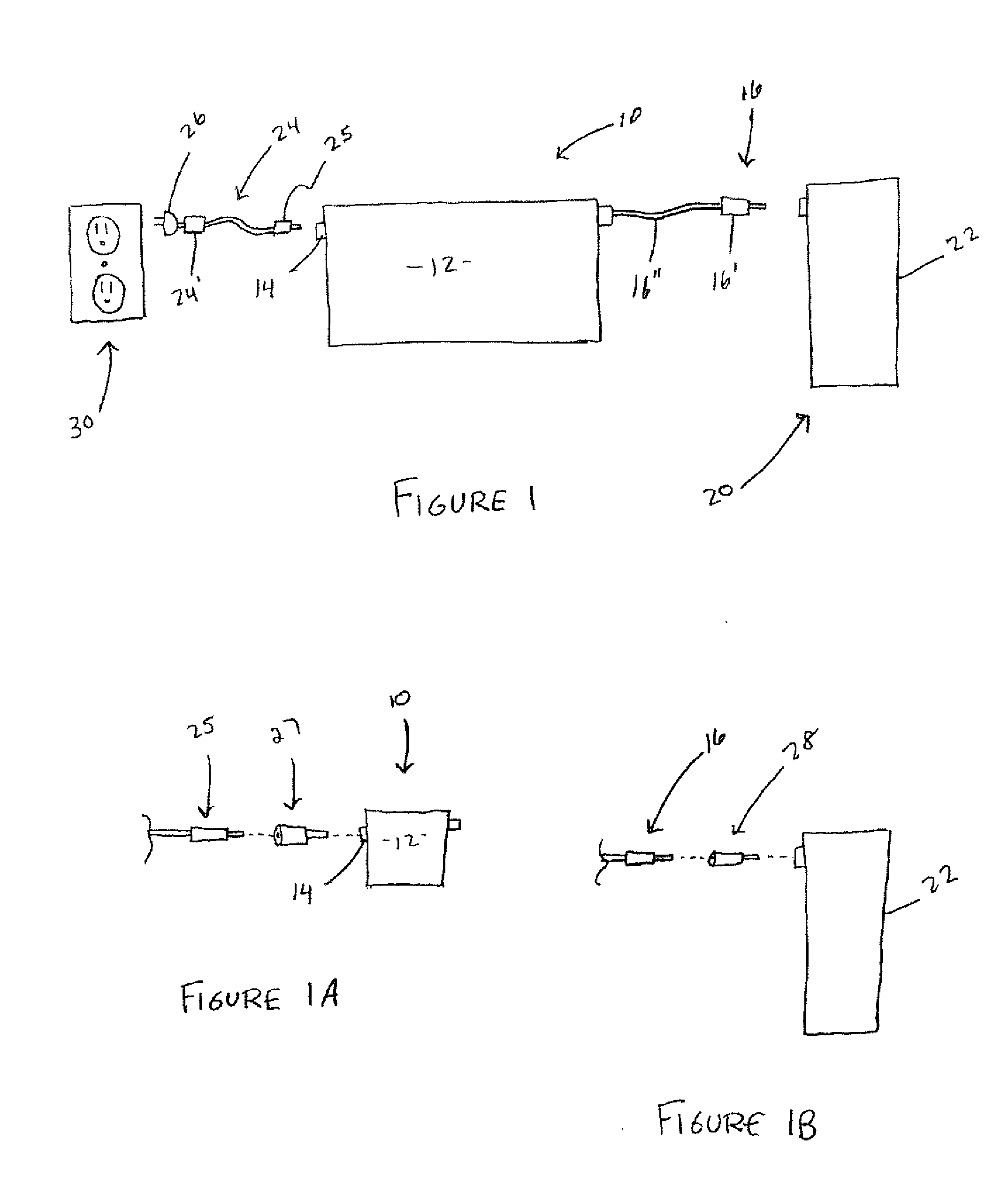
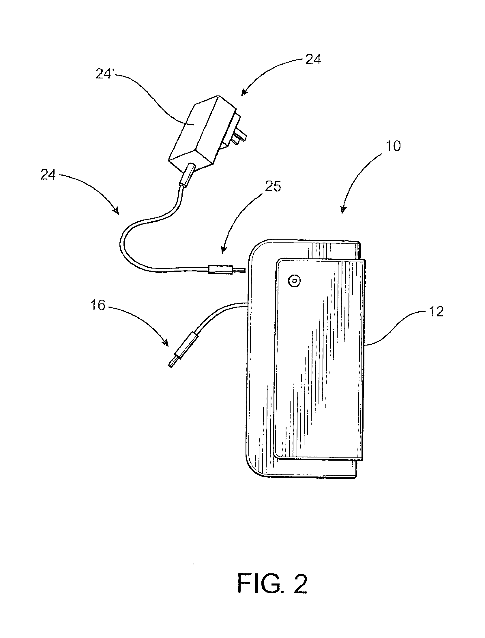
[0036]As shown in the accompanying figures, and with particular reference to FIGS. 1-3, the present invention is directed to an in-line uninterruptible power supply, generally referenced as 10, for use with an electronic device 20, wherein the electronic device 20 includes a base unit 22 and a power adapter 24. In particular, the in-line uninterruptible power supply 10 of the various embodiments of the present invention is cooperatively structured and configured to be disposed, positioned, and / or otherwise connected between the power adapter 24 and the base unit 22 of the electronic device 20.

[0037]For instance, many electronic devices 20, including, but certainly not limited to cable and DSL modems, routers, switches, desktop computers, laptop or mobile computers, printers, telephones, switch boards, security systems, cameras, etc., include a removable power adapter 24 or transformer that is structured to receive alternating current (“AC”) from a power source 30, such as a wall soc...


PUM


Abstract

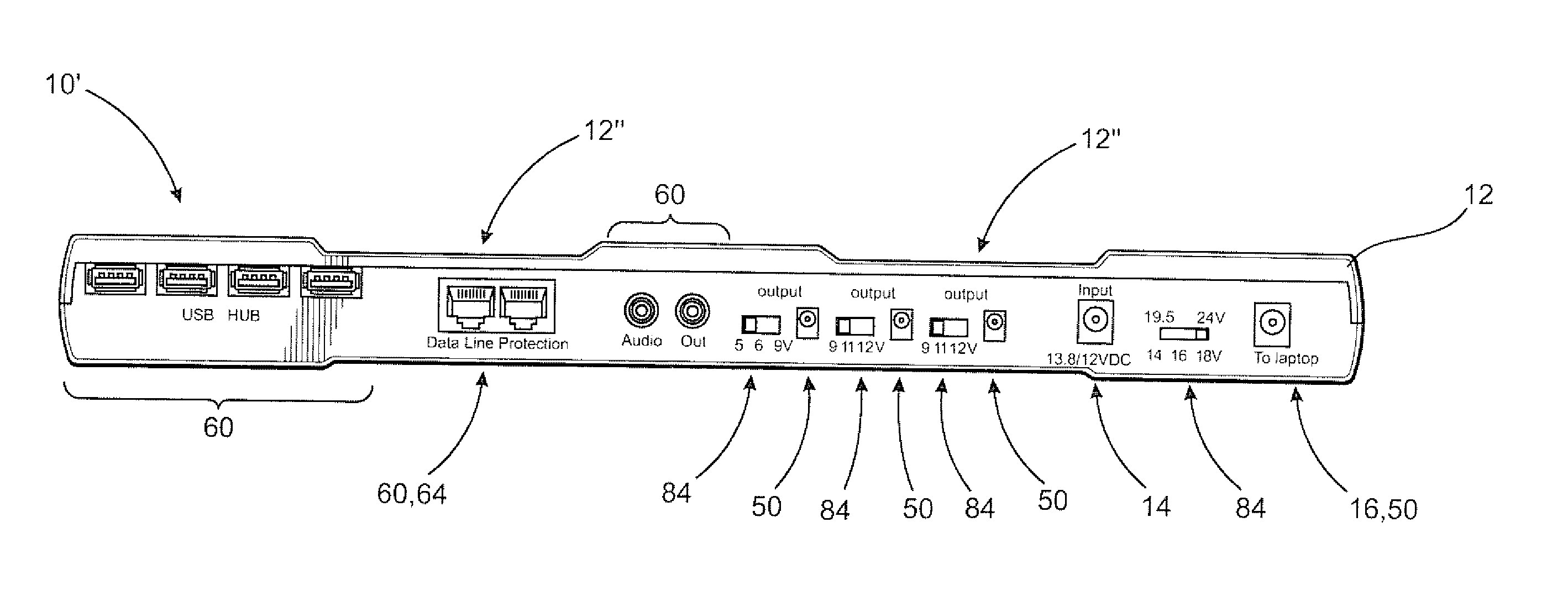
A portable power station and / or an in-line uninterruptible power supply for use with a laptop, mobile computer, netbook, notebook and other electronic devices is presented. The in-line uninterruptible power supply comprises a plurality of data ports disposed in a communicative relation with the electronic device and a plurality of power output ports for simultaneously providing power to a plurality of various electronic devices. In addition, at least one embodiment of the in-line uninterruptible power supply station is positioned between at least one of the electronic device's power adapter and the corresponding base unit, and is structured to supply continuous power to the connected electronic device(s), even in the event of a temporary power failure.

Description

CLAIM OF PRIORITY[0001]The present application is a continuation-in-part application of previously filed, now pending patent application having Ser. No. 12 / 653,978, filed on Dec. 21, 2009, and is also based on and a claim to priority is made under 35 U.S.C. Section 119(e) to a provisional patent application currently pending in the U.S. Patent and Trademark Office, having Ser. No. 61 / 314,547 and a filing date of Mar. 16, 2010, each of which are incorporated herein in their entirety by reference.BACKGROUND OF THE INVENTION[0002]1. Field of the Invention[0003]The present invention is generally directed to an in-line uninterruptible power supply for use with an electronic device having a base unit and a removable power adapter. In particular, the in-line uninterruptible power supply of the various embodiments of the present invention is cooperatively positioned between the removable power adapter and the base unit of the electronic device, which provides numerous advantages and benefit...

Claims


Application Information

Patent Timeline
Patent Type & Authority Applications(United States)
IPC IPC(8): H02J3/06G06F13/14
CPCH02J9/062H02J9/061
Inventor HERNANDEZ, MAURILIOLIANG, WEI
Owner HERNANDEZ MAURILIO
Learn More