Thermoelectric device architecture

a technology of thermoelectric devices and structures, applied in the direction of thermoelectric devices with peltier/seeback effect, thermoelectric device manufacturing/treatment, electrical apparatus, etc., can solve the problems of low operational efficiency and low operational efficiency

Inactive Publication Date: 2011-06-23
HAMILTON SUNDSTRAND CORP
View PDF17 Cites 6 Cited by
  • Summary
  • Abstract
  • Description
  • Claims
  • Application Information

AI Technical Summary

Benefits of technology

The invention is a thermoelectric device that uses conductor portions and members to transfer heat from one side of the device to the other. The conductor portions and members are angled relative to a longitudinal axis and an axis that extends perpendicular to the longitudinal axis. The heat flux and electric current flow through the device along curvilinear paths defined by the angled conductor portions and members. The technical effect of the invention is improved heat transfer with reduced thermal resistance and improved efficiency.

Problems solved by technology

The generally tortuous path leads to losses that result in low operational efficiency.
In a manner similar to that described above, the generally tortuous path leads to losses that result in low operational efficiency.

Method used


Image

  • Thermoelectric device architecture
  • Thermoelectric device architecture
  • Thermoelectric device architecture

Examples


Embodiment Construction

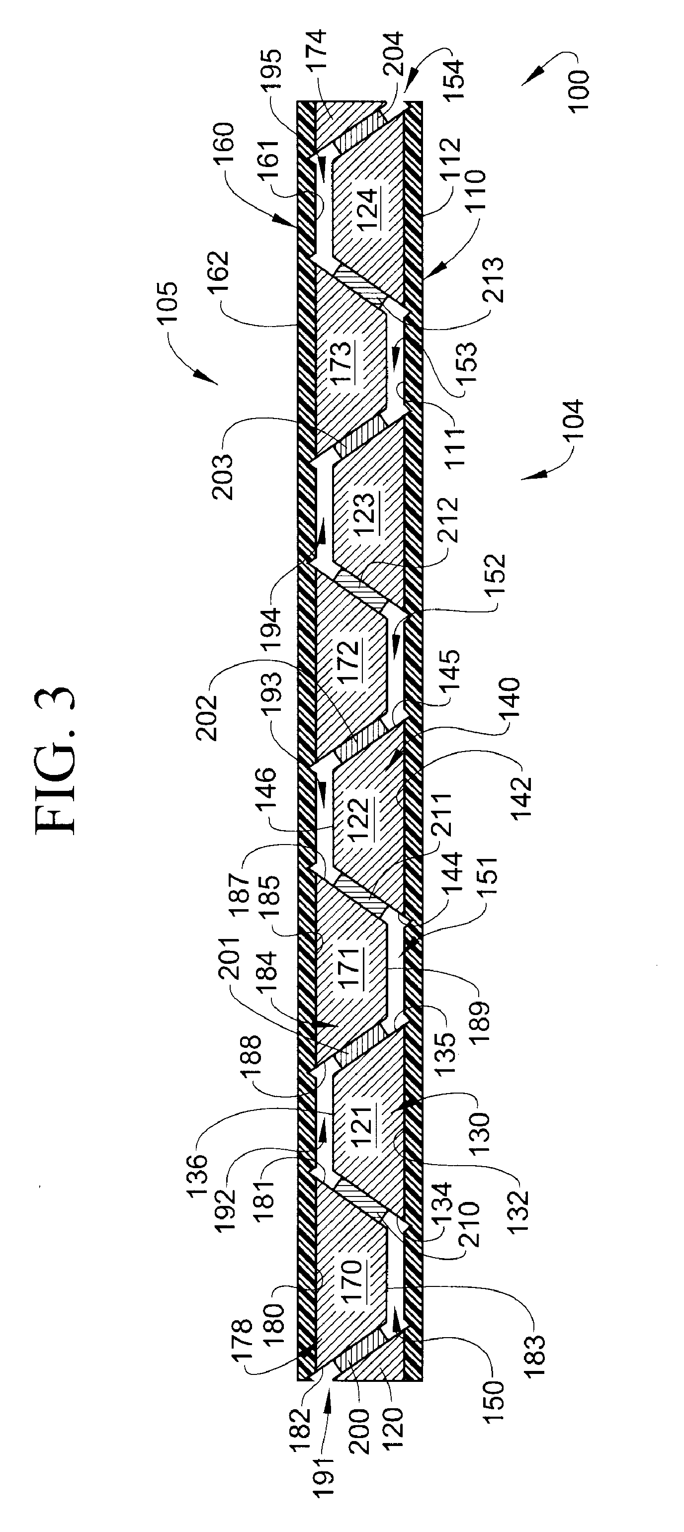
With reference to FIG. 3, a thermoelectric (TE) device constructed in accordance with an exemplary embodiment is indicated generally at 100. TE device 100 includes a hot side 104 and a cold side 105. Hot side 104 includes an electrically insulating header or insulator layer 110 having a first surface 111 and an opposing, second surface 112. A plurality of conductor leads or portions 120-124 are mounted to insulator layer 110. In the exemplary embodiment shown, conductor portion 121 includes a body portion 130 including a base portion 132 that is mounted to first surface 111. Conductor portion 121 further includes a first angled side portion 134 and a second angled side portion 135. First and second angled side portions 134 and 135 extend from base portion 132 and are joined by a third side portion 136. First and second angled side portions 134 and 135 are arranged at an angle relative to a longitudinal axis defined by insulator layer 110, and relative to an axis that extends perpend...


PUM


Abstract

A thermoelectric device (100, 220) includes a plurality of conductor portions (120-124) including a first angled side portion (134) and a second angled side portion (135). The thermoelectric device (100, 220) also includes a plurality of conductor members (170-174) including a first angled side section (181) and a second angled side section (182). A plurality of P-type thermoelectric members (210-213) interconnect corresponding ones of the first angled side portions (134) with the first angled side sections (181). A plurality of N-type thermoelectric members (200-204) interconnect corresponding ones of the second angled side portions (135) with the second angled side sections (182). Electric flow through the plurality of conductor portions (120-124) and the plurality of conductor members (170-174) passes along a first predefined curvilinear path and a heat flux passes along a second predefined curvilinear path.

Description

BACKGROUND OF THE INVENTIONThe subject matter disclosed herein relates to thermoelectric devices and, more particularly, to an architectural configuration of a thermoelectric device.Thermoelectric devices include thermoelectric coolers that operate according to the Peltier effect in which an electrical input is transformed to a heat flux, and thermoelectric generators that operate according to the Seebeck effect in which a heat flux is transformed to an electrical output. Thermoelectric heat pumps or coolers are solid-state devices that use the Peltier effect to create a heat flux between junctions of two different types of materials. Heat is transferred from one side of the device to another side of the device against a thermal gradient with the consumption of electrical energy. Conversely, thermoelectric generators are solid-state devices that convert a heat flux between first and second sides into electrical energy. Both thermoelectric coolers and thermoelectric generators operat...

Claims


Application Information

Patent Timeline
Patent Type & Authority Applications(United States)
IPC IPC(8): H01L35/34H01L35/28H10N10/00H10N10/10H10N10/01H10N10/13H10N10/17
CPCH01L35/32H10N10/17
Inventor ST. ROCK, BRIANKASLUSKY, SCOTT F.
Owner HAMILTON SUNDSTRAND CORP
Why Eureka
Try Eureka