Eureka AIR delivers breakthrough ideas for toughest innovation challenges, trusted by R&D personnel around the world.

Sensor having an internal calibration structure

a technology of internal calibration and sensor, applied in the field of sensors, can solve problems such as impossible cases and the most complex parts

Inactive Publication Date: 2011-06-23
KISTLER HLDG AG
View PDF1 Cites 3 Cited by
  • Summary
  • Abstract
  • Description
  • Claims
  • Application Information

AI Technical Summary

Benefits of technology

The present invention provides a way to test and calibrate sensors without disassembling them. This is done by using a test or calibration structure that converts a pressure or calibration pressure into a force acting on the sensor's measuring element. This force can be applied without interrupting the sensor's measurement function and without adding expensive additional apparatus. The test force can be applied as a test pulse and changes in sensor behavior can be measured and used for testing or recalibration. Disassembly of the sensor for testing or calibration is unnecessary.

Problems solved by technology

For the most part, this takes place by means of the application of a known load from outside, which is for the most part complex and in some cases impossible, because for example, the sensors are not accessible to such a test load without disassembly.

Method used


Image

  • Sensor having an internal calibration structure
  • Sensor having an internal calibration structure
  • Sensor having an internal calibration structure

Examples


Embodiment Construction

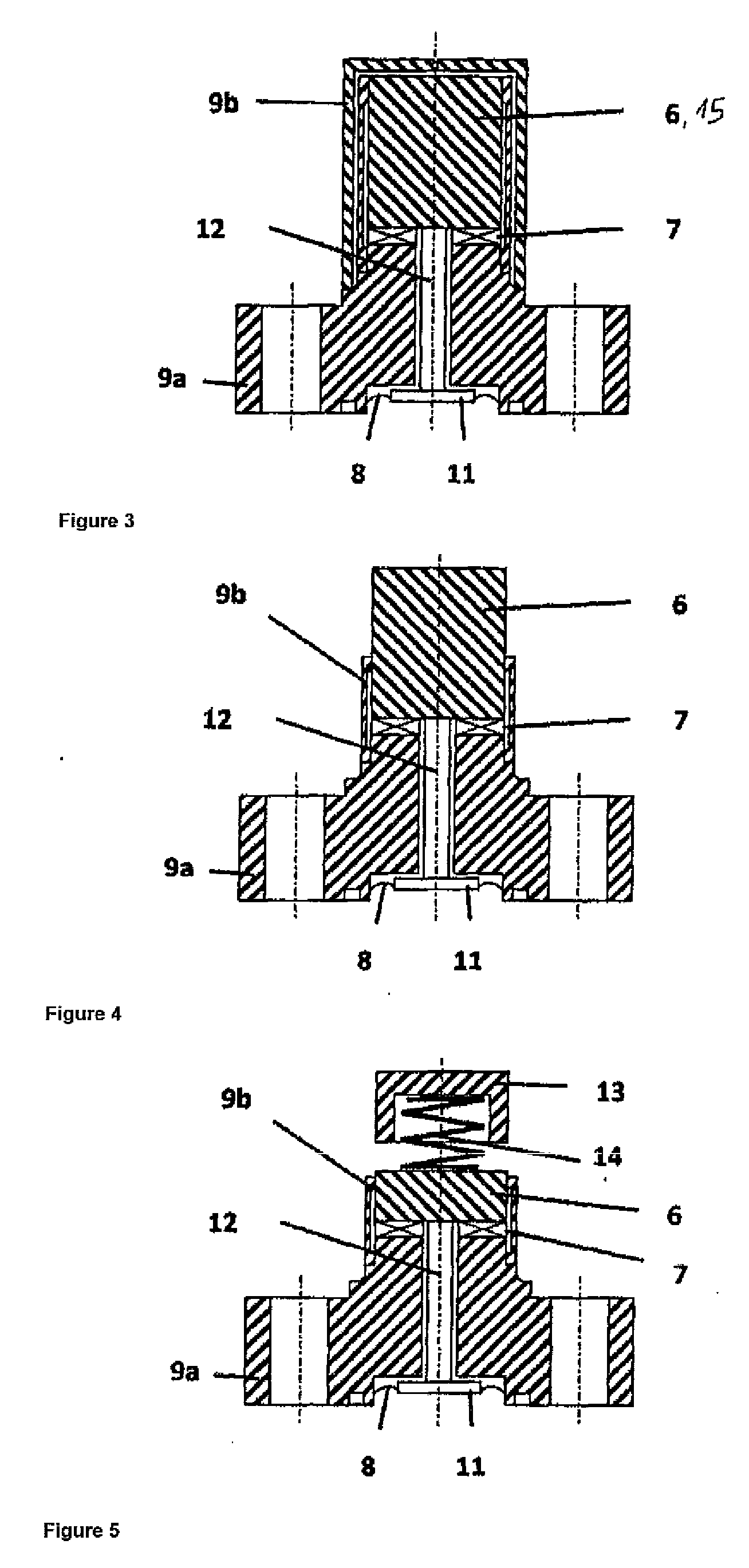
[0017]The sensor in FIG. 1 is configured for integration into an assembly point 1 which, in addition to a fixing thread 2 also has an inflow hole 3a for the pressure-transmitting medium or the test pressure. From this inflow hole, the pressure medium producing the test pressure is conveyed via the assembly gap 4, which is sealed by means of two O-rings 5, into the sensor, next into the annular channel 3b and then via the short hole 3c to the piston 6. The annular channel 3b has the advantage that the inflow hole 3a may open at any desired point on the annular channel circumference. The measurement mass 15 in this example acts as a pressure piston 11 and as force introduction 6 for the measuring element 7. By loading the pressure piston / measurement mass / pressure introduction part with the test pressure, a test pressure is generated on the measuring element 7. A sealing membrane 8 seals the measuring element 7 against disturbances caused by the pressure medium.

[0018]In FIG. 2, a simil...


PUM

PropertyMeasurementUnit
pressureaaaaaaaaaa
elasticaaaaaaaaaa
forceaaaaaaaaaa

Abstract

A sensor has a measuring element that measures forces. The measuring element measures direct forces or measurement variables which are converted into forces by means of a measurement variable converter in the sensor. The sensor includes a structure that converts test pressure guided into the sensor into a test force that stresses the measuring element in the same manner as the phenomenon that is to be measured by the sensor.

Description

CROSS-REFERENCE TO RELATED APPLICATIONS[0001]This application claims priority to International Application Serial No. PCT / EP2009 / 006005 filed Aug. 19, 2009, which claims priority to Austrian Application No. AT 1286 / 2008 filed Aug. 19, 2008.TECHNICAL FIELD[0002]The invention relates to a sensor in which the value to be measured is a force or a value such as for example acceleration or path which is converted by means of components of the sensor into force, the measuring element, which is the element forming the measurement signals, in each case converting this force into the measurement signal, it being possible for the nature of the reaction to this force to vary very widely, e.g. charge output, voltage change, displacement, etc., or sensors which must be calibrated during operation.BACKGROUND[0003]There are many sensors in which the value to be measured exerts a force on the measuring element of the sensor. For the most part, force sensors conduct the value to be measured directly ...

Claims


Application Information

Patent Timeline
Patent Type & Authority Applications(United States)
IPC IPC(8): G01L27/00G01L7/16
CPCG01L25/00G01L27/005G01P21/00
Inventor GLASER, JOSEF
Owner KISTLER HLDG AG
Why Eureka
Eureka Blog
Learn More