
Switch structure and associated circuit

a switch structure and switch technology, applied in the field of micro-electromechanical switch structures, can solve the problems of large circuit breakers, large circuit breakers, and large circuit breakers, and achieve the effect of minimal characteristic resistan

Active Publication Date: 2011-06-16
GENERAL ELECTRIC CO
View PDF18 Cites 9 Cited by
  • Summary
  • Abstract
  • Description
  • Claims
  • Application Information

AI Technical Summary

Benefits of technology

[0005]In one aspect, an apparatus, such as a switch module, is provided. The apparatus can include an electromechanical switch structure configured to move between an open configuration and a fully-closed configuration over a characteristic time (e.g., less than or equal to about 15 microseconds). When in the fully-closed configuration, the electromechanical switch structure can have a minimum characteristic resistance.

Problems solved by technology

Traditionally, many conventional circuit breakers include bulky (macro-)electromechanical switches.
Unfortunately, these conventional circuit breakers are large in size may necessitate use of a large force to activate the switching mechanism.
Additionally, the switches of these circuit breakers generally operate at relatively slow speeds.
Furthermore, these circuit breakers can be complex to build and thus expensive to fabricate.
Moreover, energy associated with the arc may seriously damage the contacts and / or present a burn hazard to personnel.
However, since solid-state switches do not create a physical gap between contacts when they are switched into a non-conducting state, they experience leakage current when nominally non-conducting.
Furthermore, solid-state switches operating in a conducting state experience a voltage drop due to internal resistances.
Both the voltage drop and leakage current contribute to power dissipation and the generation of excess heat under normal operating circumstances, which may be detrimental to switch performance and life.
Moreover, due at least in part to the inherent leakage current associated with solid-state switches, their use in circuit breaker applications is not possible.

Method used


Image

  • Switch structure and associated circuit
  • Switch structure and associated circuit
  • Switch structure and associated circuit

Examples


Embodiment Construction

[0025]Example embodiments of the present invention are described below in detail with reference to the accompanying drawings, where the same reference numerals denote the same parts throughout the drawings. Some of these embodiments may address the above and other needs.

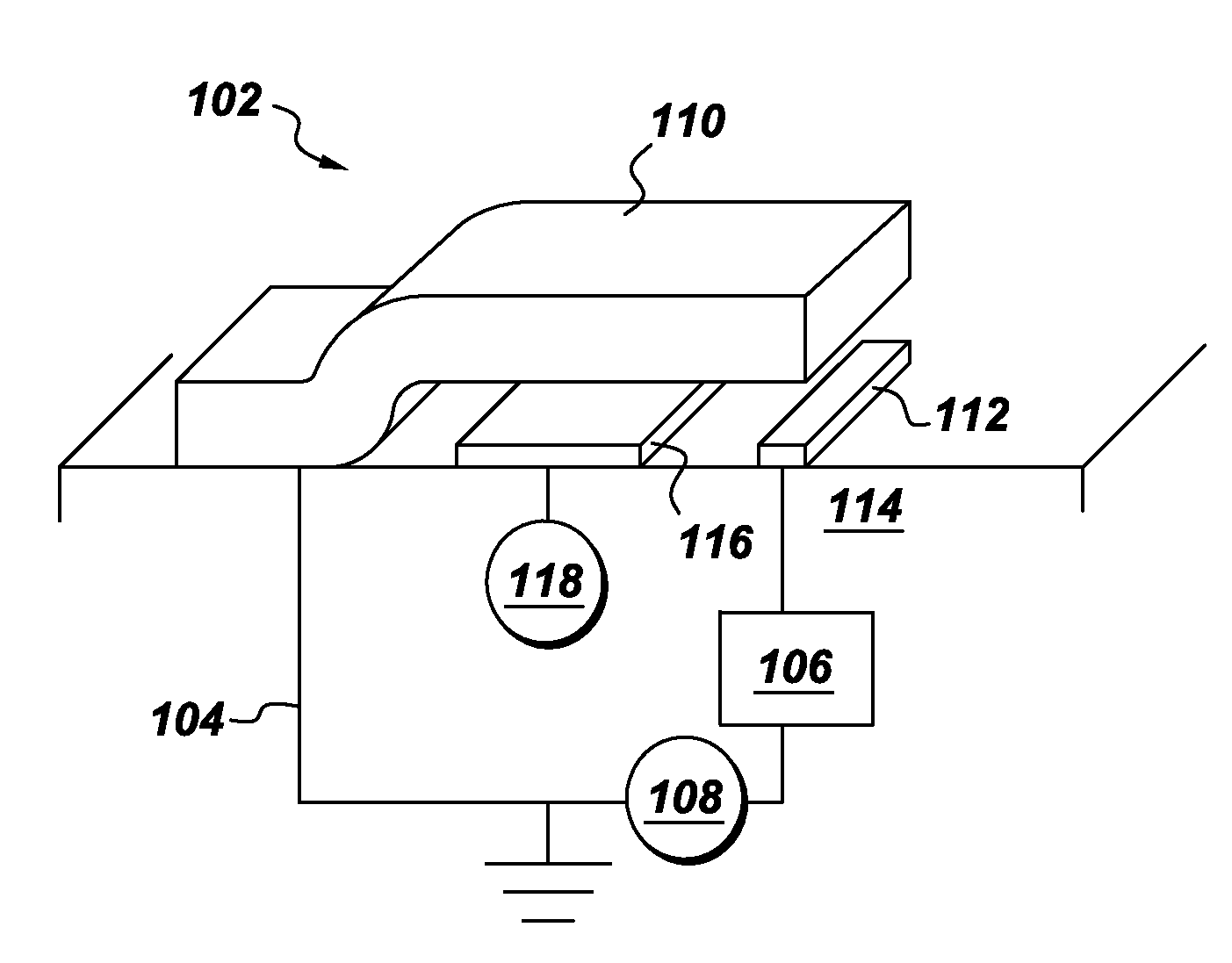
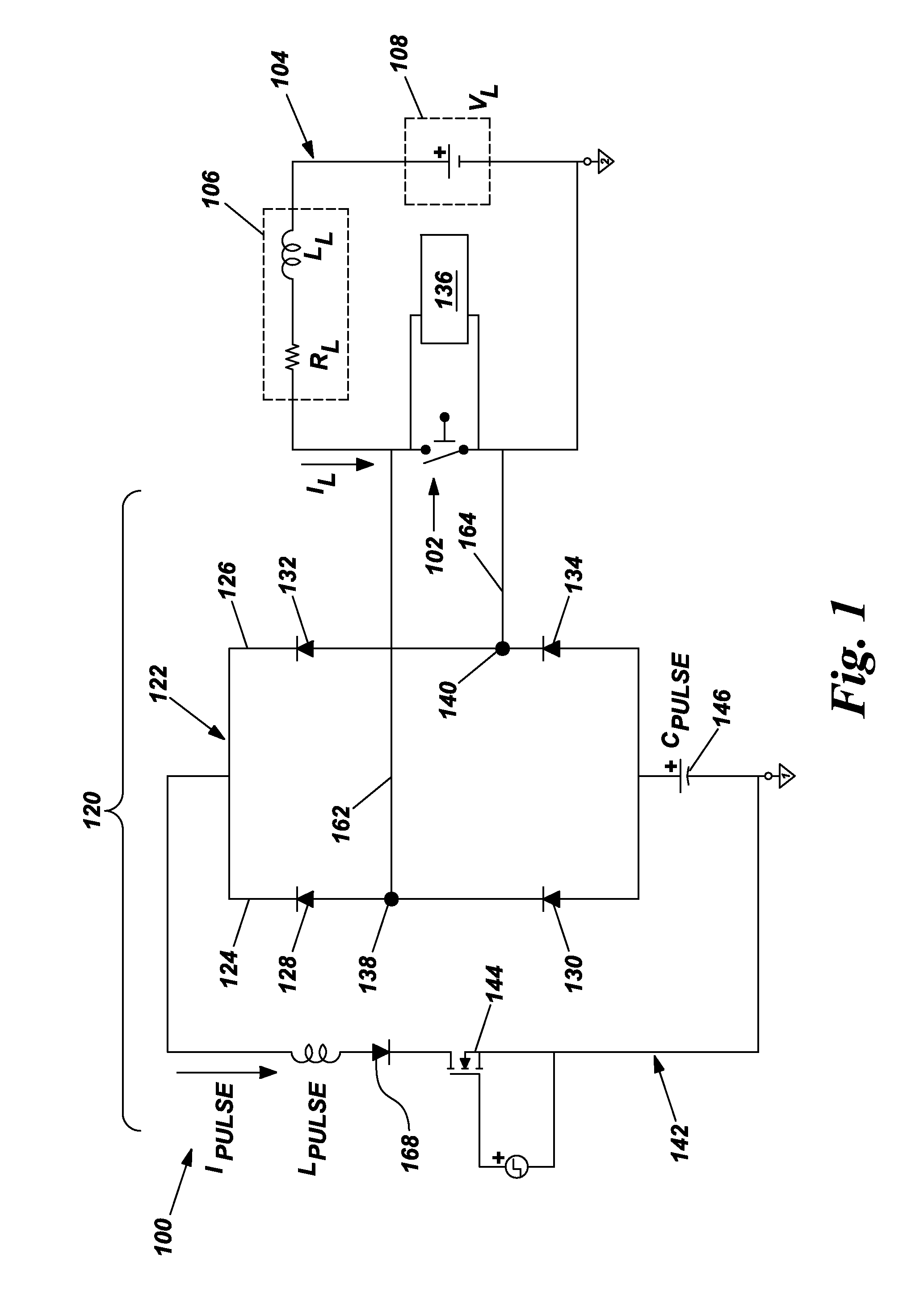
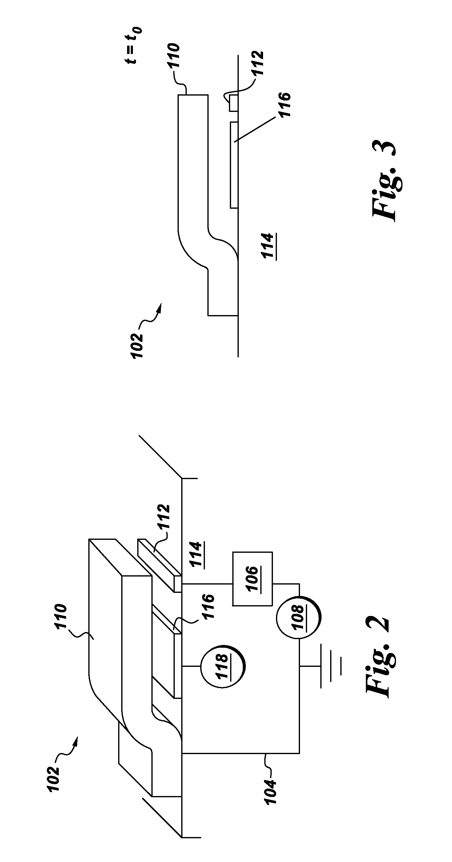
[0026]Referring to FIG. 1, therein is shown an apparatus, such as a switch module 100 (e.g., for use in conjunction with motor starter applications), configured in accordance with an example embodiment. The switch module 100 can include an electromechanical switch structure, such as a microelectromechanical switch or a microelectromechanical system (MEMS) switch 102. The MEMS switch 102 can be incorporated as part of a load circuit 104 that also includes, for example, an electrical load 106 characterized by a load inductance LL and a load resistance RL. It is noted that the load circuit 104 may also include inherent inductance and resistance, and these will contribute to, and will be considered to be included in, the...


PUM


Abstract

An apparatus, such as a switch module, is provided. The apparatus can include an electromechanical switch structure configured to move between an open configuration and a fully-closed configuration (associated with a minimum characteristic resistance) over a characteristic time. A commutation circuit can be connected in parallel with the electromechanical switch structure, and can include a balanced diode bridge configured to suppress arc formation between contacts of the electromechanical switch structure and a pulse circuit including a pulse capacitor configured to form a pulse signal (in connection with a switching event of the electromechanical switch structure) for causing flow of a pulse current through the balanced diode bridge. The electromechanical switch structure and the balanced diode bridge can be disposed such that a total inductance associated with the commutation circuit is less than or equal to a product of the characteristic time and the minimum characteristic resistance.

Description

BACKGROUND[0001]Embodiments of the invention relate generally to devices for switching current, and more particularly to microelectromechanical switch structures.[0002]A circuit breaker is an electrical device designed to protect electrical equipment from damage caused by faults in the circuit. Traditionally, many conventional circuit breakers include bulky (macro-)electromechanical switches. Unfortunately, these conventional circuit breakers are large in size may necessitate use of a large force to activate the switching mechanism. Additionally, the switches of these circuit breakers generally operate at relatively slow speeds. Furthermore, these circuit breakers can be complex to build and thus expensive to fabricate. In addition, when contacts of the switching mechanism in conventional circuit breakers are physically separated, an arc can sometimes form therebetween, which arc allows current to continue to flow through the switch until the current in the circuit ceases. Moreover,...

Claims


Application Information

Patent Timeline
IPC IPC(8): H01H9/54
CPCH01H1/0036H01H2071/008H01H59/0009H01H9/542H03K17/687
Inventor GOWDA, ARUN VIRUPAKSHAO'BRIEN, KATHLEEN ANNPARK, JOHN NORTONPREMERLANI, WILLIAM JAMESSCHELENZ, OWEN JANNIS SAMUELSUBRAMANIAN, KANAKASABAPATHI
Owner GENERAL ELECTRIC CO
Learn More