
Preassembly and integration of aircraft cabins

a technology for aircraft cabins and components, applied in the field of aircraft cabin assembly and integration, can solve the problems of long assembly time and significant increase in assembly effort, and achieve the effect of shortening the assembly time of the aircraft structure and the aircraft cabin

Active Publication Date: 2011-06-16
AIRBUS OPERATIONS GMBH
View PDF11 Cites 18 Cited by
  • Summary
  • Abstract
  • Description
  • Claims
  • Application Information

AI Technical Summary

Benefits of technology

[0009]It is an object of the invention to shorten the assembly time of the aircraft structure and the aircraft cabin.
[0013]Thus the aircraft structure and parts, or even the entire aircraft cabin can be pre-assembled in parallel at various locations. As a result of the pre-assembly of the cabin, parallelisation of the assembly activities and thus shortening of the throughput time can be made possible.
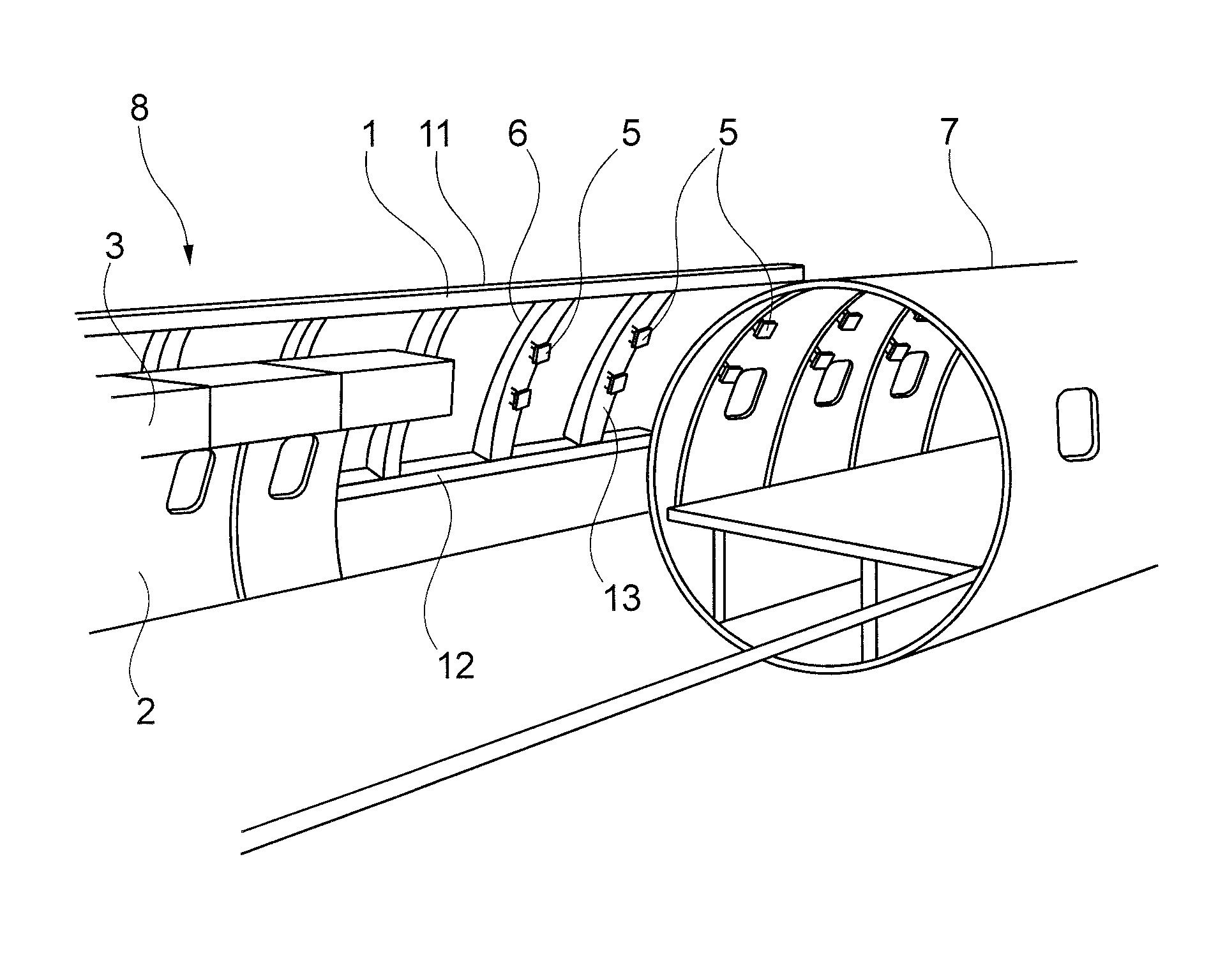
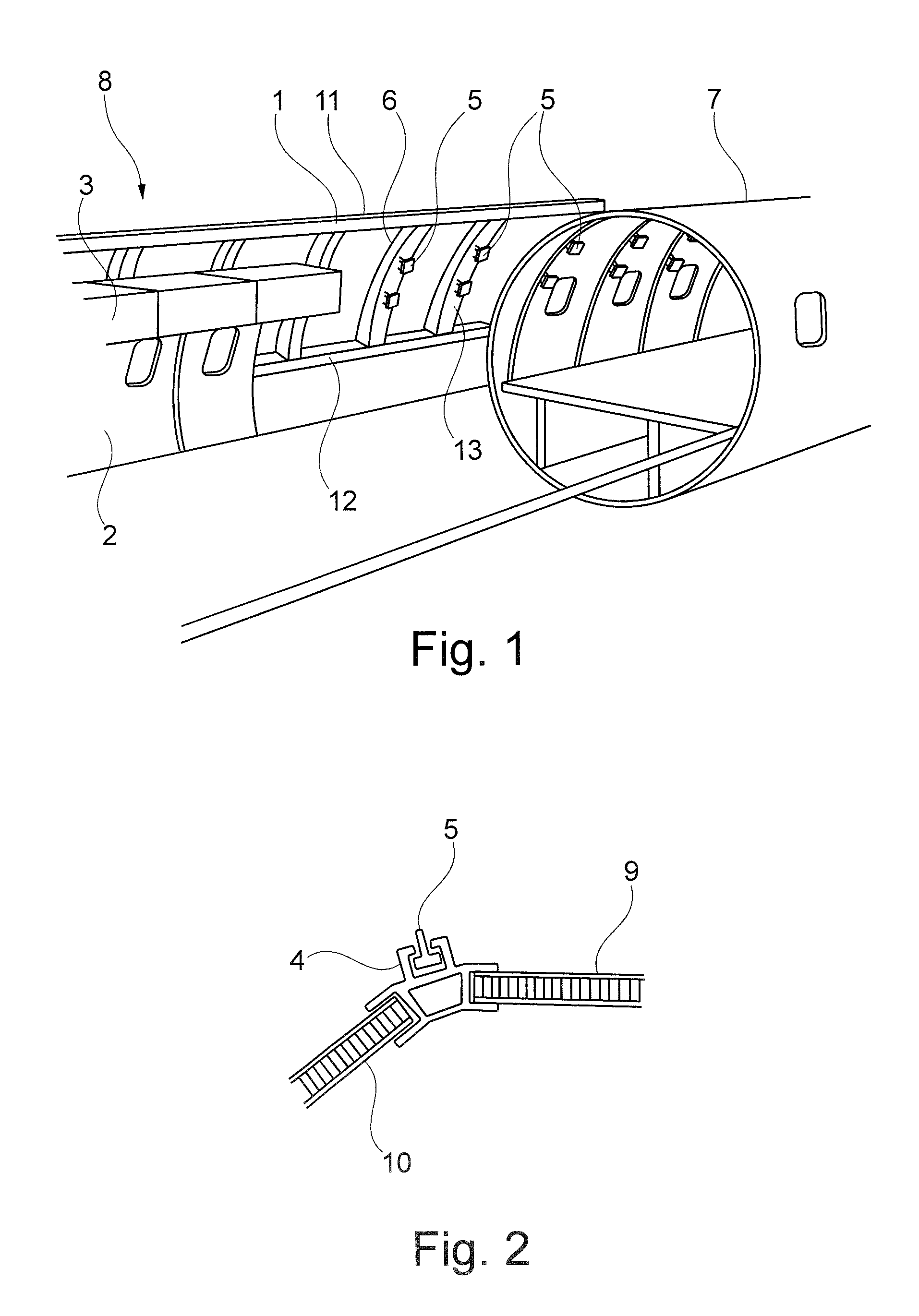
[0018]According to a further exemplary embodiment of the invention, the assembly frame corresponds to the aircraft structure, i.e. replicates the aircraft structure. This results in the part or parts of the aircraft cabin that is / are to be pre-assembled, or in the entire aircraft cabin that is to be pre-assembled, being attached to the assembly frame in principle in precisely the same manner as is the case later in the corresponding section of the aircraft structure. To this effect the assembly frame can be connected directly to the aircraft structure, or at least it can be arranged directly beside said aircraft structure, so that subsequent transfer (sliding) of the pre-assembled parts, or of the pre-assembled part, of the aircraft cabin into the open section of the aircraft structure can be carried out in a simple manner without in this process subjecting the pre-assembled part to significant mechanical loads.
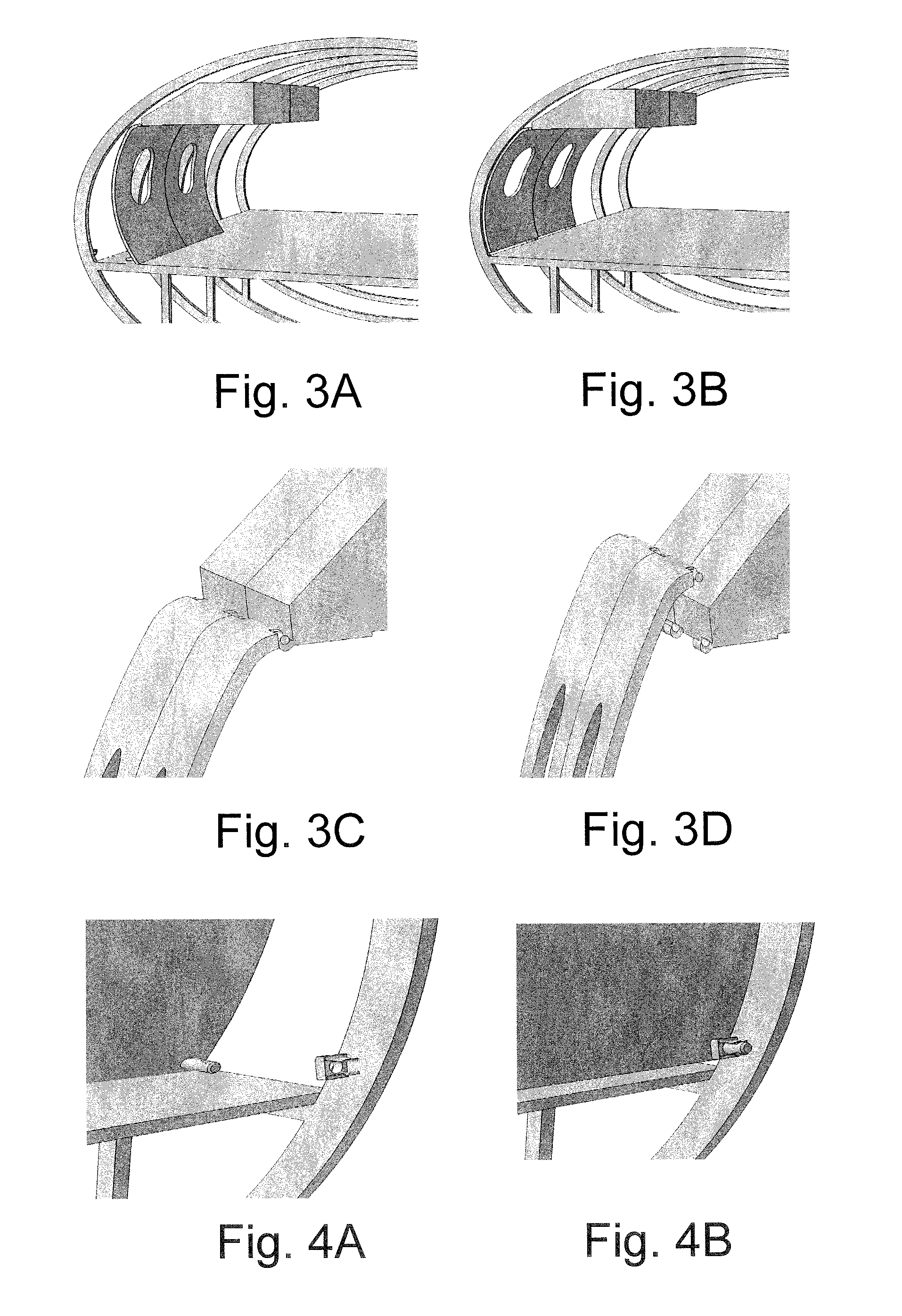
[0021]Furthermore, it is possible for the retaining member to be designed, for example, in the form of a roll that runs on the rail. Furthermore, it is possible to remove the retaining members and / or the rails after final installation of the aircraft cabin in the aircraft structure. Moreover, it is possible to design the retaining members and / or the rails in such a manner that they can be used as attachment points for attaching the aircraft cabin to the aircraft structure. In this manner further installation expenditure can be saved.

Problems solved by technology

A substantial percentage of the costs and of the throughput time of aircraft relates to the final assembly of the cabin.
The multitude of lining panels, overhead stowage bins and components of the supply duct that are to be assembled in the aircraft result in long throughput times.
However, this results in a significant increase in assembly effort.

Method used


Image

  • Preassembly and integration of aircraft cabins
  • Preassembly and integration of aircraft cabins
  • Preassembly and integration of aircraft cabins

Examples


Embodiment Construction

[0037]The illustrations in the figures are diagrammatic and not to scale.

[0038]In the following description of the figures the same reference characters are used for identical or similar elements.

[0039]FIG. 1 shows a diagrammatic view of an aircraft structure 7 and of an assembly device 8 that corresponds to, in other words is attuned to, said aircraft structure 7. The assembly device 8 comprises an assembly frame 1. The assembly frame 1 comprises, for example, several parallel segments 11, 12 that are arranged so as to be essentially horizontal, as well as transverse segments (see for example reference characters 6 and 13) that are placed vertically to the aforesaid and reproduce the aircraft structure.

[0040]On the transverse segments 6, 13 and also on the aircraft ribs, i.e. on the frame elements and / or stringers of the aircraft structure 7, retaining members 5 are attached.

[0041]These retaining members 5 engage corresponding rails that are attached to the pre-installed aircraft c...


PUM


Abstract

According to an exemplary embodiment of the invention, pre-assembly and integration of part of an aircraft cabin takes place outside the aircraft structure by means of an assembly device. After pre-assembly, the part of the aircraft cabin is slid into the open section of the aircraft structure where it is installed.

Description

REFERENCE TO RELATED APPLICATIONS[0001]This application claims the benefit of the filing date of U.S. Provisional Application No. 61 / 188,815, filed Aug. 13, 2008, and of German Patent Application No. 10 2008 038 806.8, filed Aug. 13, 2008, the disclosures of which applications are hereby incorporated herein by reference.FIELD OF THE INVENTION[0002]The invention relates to the assembly and integration of aircraft cabins. In particular, the invention relates to an assembly device for the pre-assembly and integration of at least part of an aircraft cabin in an aircraft structure, to an aircraft-component assembly system and to a method for the pre-assembly and integration of at least part of an aircraft cabin in an aircraft structure.BACKGROUND TO THE INVENTION[0003]A substantial percentage of the costs and of the throughput time of aircraft relates to the final assembly of the cabin. The multitude of lining panels, overhead stowage bins and components of the supply duct that are to be...

Claims


Application Information

Patent Timeline
IPC IPC(8): B64F5/00B23P19/00B23P11/00
CPCB64F5/00B64F5/0009Y10T29/53548Y10T29/49622Y10T29/53539Y10T29/49616Y10T16/364Y10T29/49828Y10T16/379B64F5/10
Inventor BLEES, CHRISTOPHHALFMANN, NIKLASKRAUSE, DIETERGEHM, MARCUS
Owner AIRBUS OPERATIONS GMBH
Learn More