
Methods and systems for real time RFID locating onboard an aircraft

a technology of real-time rfid locating and aircraft, applied in the field of tracking and inventory of items on aircraft, can solve the problems of complex systems that utilize components having significant weight or require significant computing resources, and the active rfid tag is 1000 times more expensive per tag than the passive rfid tag

Active Publication Date: 2011-06-09
THE BOEING CO
View PDF19 Cites 47 Cited by
  • Summary
  • Abstract
  • Description
  • Claims
  • Application Information

AI Technical Summary

Benefits of technology

[0009]The features, functions, and advantages that have been discussed can be achieved independently in various embodiments of the present invention or may be combined in yet other embodiments further details of which can be seen with reference to the following description and drawings.

Problems solved by technology

Such systems have disadvantages and other limitations when applied to an aircraft environment.
Specifically, such complex systems utilize components having significant weight or require significant computing resources for signal processing, which is always a concern or limitation in the aircraft environment.
Although simpler system solutions can utilize active RFID tags, these active RFID tags are 1000 times more expensive per tag than passive RFID tags.
However, the active RFID tags require tag batteries, and have very limited accuracy and resolution capabilities.
RFID systems that incorporate the less expensive passive RFID tags are complex, dedicated tracking solutions, with bulky and heavy smart antennas, as described above.
Digital networks of RFID tag readers have limited capabilities to estimate time difference of arrival for RFID tag location finding due to delays embedded in the digital network system solutions.

Method used


Image

  • Methods and systems for real time RFID locating onboard an aircraft
  • Methods and systems for real time RFID locating onboard an aircraft
  • Methods and systems for real time RFID locating onboard an aircraft

Examples


Embodiment Construction

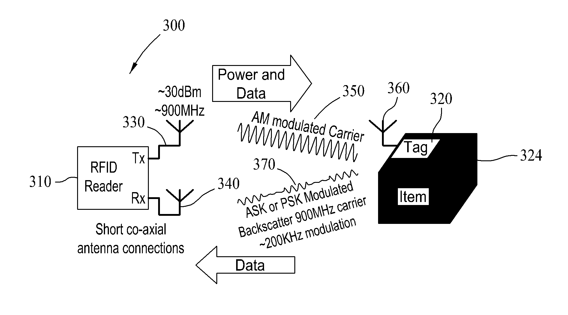
[0017]Accurate, real time locating (RTLS) of low cost passive RFID tags onboard an aircraft provide an ability to locate, for example, passengers, baggage, confirm a full complement of life vests, maintain an inventory of portable onboard items, and enable physical position location mapping of totally wireless electronic devices (e.g. sensors) to logical network addresses for cabin services.

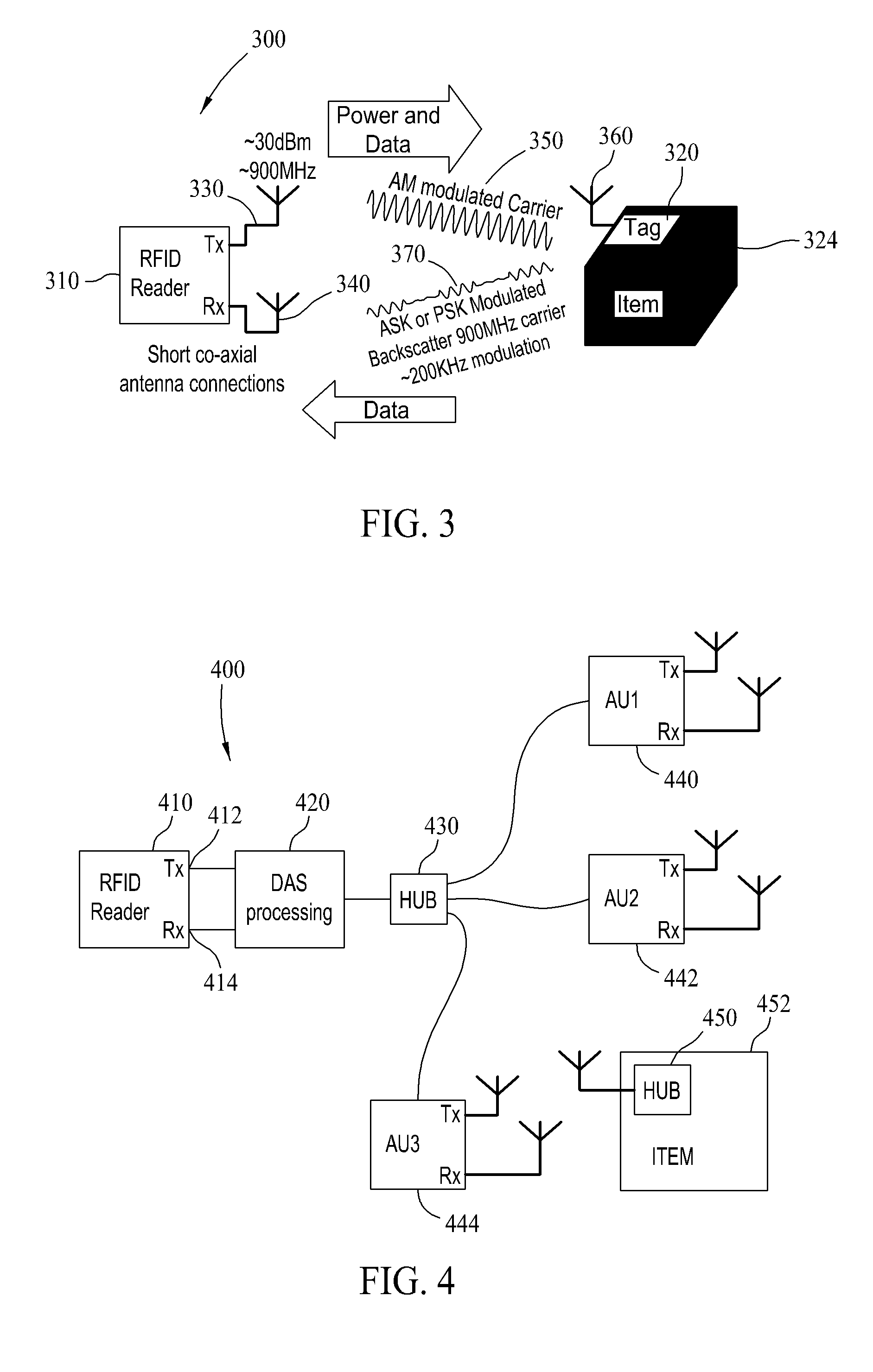
[0018]Embodiments are directed to an onboard passive RFID system based on a distributed antenna system (DAS) optimized to reduce nulls and increase received signal strengths throughout an aircraft. Such a system enables the identifying of items in a radio fingerprinted cabin, multi-antenna locating techniques to improve the absolute locating accuracy of passive RFID tags to within a single seat or seat group in one example. In addition, the utilization of the DAS provides a broadband system which allows a wide range of wireless communication services to be transmitted over a single distribution i...


PUM


Abstract

An aircraft communications and item tracking system is described. The system includes an RFID reader and a communications device located at fixed locations within the aircraft, a plurality of passive RFID tags operable for association with items within the aircraft, and a distributed antenna system comprising a plurality of antenna units and a wireless distribution system. The wireless distribution system is communicatively coupled to an aircraft communications network. The antenna units are communicatively coupled to the wireless distribution system and disbursed about the aircraft such that the RFID tags within the aircraft may be activated by signals output by at least one of the antenna units. The RFID reader and communications device are communicatively coupled to the wireless distribution system. The distributed antenna system is operable for transmission and reception of signals associated with the RFID reader and RFID tags. The distributed antenna system is further operable for transmission and reception of signals associated with the communications device.

Description

BACKGROUND[0001]The field of the invention relates generally to the tracking and inventory of items on an aircraft, and more specifically, to methods and systems for real time RFID locating onboard an aircraft.[0002]Existing inventory and tracking solutions based on active RFID and WiFi use signal strength measurements and time difference of arrival algorithms to determine location coordinates. More recently, broadband wireless location beacon signals have been used to overcome areas of poor WiFi coverage. One system uses a network of RFID readers and their dedicated processors and software to locate tags among a dedicated network of RFID readers. Another solution uses software controlled smart antennas to steer beams, and perform signal acquisition and source location using an array of elements, an array controller, plus an RFID reader module, weighing 50 to 85 lbs per antenna. Still another system requires placement of transmitters near tags and sophisticated signal processing to ...

Claims


Application Information

Patent Timeline
IPC IPC(8): G06K7/01
CPCG06K7/0008G06K7/10079G06K2017/0051G06K7/10346G06K2017/0045G06K7/10316
Inventor KRUG, WILLIAM P.SHETTY, SUDHAKAR S.KIRKLAND, DAVID T.
Owner THE BOEING CO
Learn More