Backrest structure

a backrest and structure technology, applied in the field of chairs, can solve the problems of many problems to be solved, the random placement of chairs on the chair, and the fixed volume of pads, etc., and achieve the effect of convenient fixed

Inactive Publication Date: 2011-06-09
NITRING ENTERPRISE
View PDF0 Cites 8 Cited by
  • Summary
  • Abstract
  • Description
  • Claims
  • Application Information

AI Technical Summary

Benefits of technology

[0008]The object of the present invention is to provide a backrest structure that not only can make its position fixed but adjustable on a chair, but also can make the thickness of its pad for supporting adjustable, and can have a function of hot compress, so that it can get an object of having multiple functions.
[0012]In practicing, the appearance of the connecting part can be generally a planar board, the connecting part is provided with a first connecting unit, and in the receiving opening, a second connecting unit is movably connected with the first connecting unit, the second connecting unit includes a pair of zippers, while the first connecting unit includes a pair of engaging members for the zippers; the connecting part can be displaced relatively to the receiving opening by using the engaging members to pull to open or to close the zippers; further by virtue that the connecting part is inserted into the receiving opening in a closely fitting mode, after the connecting part is received in the receiving opening to movably connect therewith, a positioning function to prevent sliding by friction can be obtained.
[0014]When the pad is placed on a chair such as a sofa, the fixing portion can be inserted in a seam of a chair to render the lazy back of the chair to be clamped between the connecting part and the fixing portion by the elastic clamping force, so that an effect of having the pad fixed on the chair can be attained; moreover, when the pad is placed on a chair such as an office chair, the two sides of the back clip are stretched away to have the fixing portion clung on the upper area of the rear side of the chair lazy back by the clamping force stated above, and to have the connecting part clung together with the pad on the front side of the chair lazy back, thereby the pad is fixed on the upper area of the chair lazy back, and by using the above mentioned connecting part to adjust the relative position of the pad to the back clip, an object that the pad is held and is adjustable on the chair can be obtained.
[0015]Additionally, in order to increase the practicality of use of the pad of the present invention, the pad is endued with a function of hot compress; in practicing, the pad can be provided between the above mentioned outer envelopment and inner lining material with a heat emitting element, and the outer envelopment is provided on one of its lateral sides with a control unit which can be connected with an electric power source to supply electricity for the heat emitting element and can control heating temperature of the heat emitting element to make the pad get the function of hot compress.
[0017]And moreover, in practicing, the pad can be provided therein with a heat sinking element, and can be provided on the outer surface of it with a control member; wherein the control member can be connected with an electric power source to provide electric power for the heat sinking element for operation, the control member controls the heat sinking element to render the latter to blow air for a user to increase comfort of the user, thereby the pad can get an object of having multiple functions.
[0018]As compared with the conventional technique, the backrest structure of the present invention can be conveniently fixed but adjustable on the chair, and can have a function of hot compress as well as adjusting the thickness of the pad for supporting; thereby the pad can get a feeling of comfort and being most suitable for seating, and can get an object of having multiple functions.

Problems solved by technology

Although the above pad can help a user to get more comfortable feeling of seating, in using the pad, quite many problems are to be solved.
For example, the pad can only be placed randomly on a seating cushion, but is unable to have its height adjusted according to requirement of the user; every user has his own size of body concerning height, stoutness etc., and his own customary declination angle or orientation in seating; in view of these, a pad with a fixed volume and being placed on the chair randomly is unable to be satisfied by different people in their requirement in seating.

Method used


Image

  • Backrest structure
  • Backrest structure
  • Backrest structure

Examples


Embodiment Construction

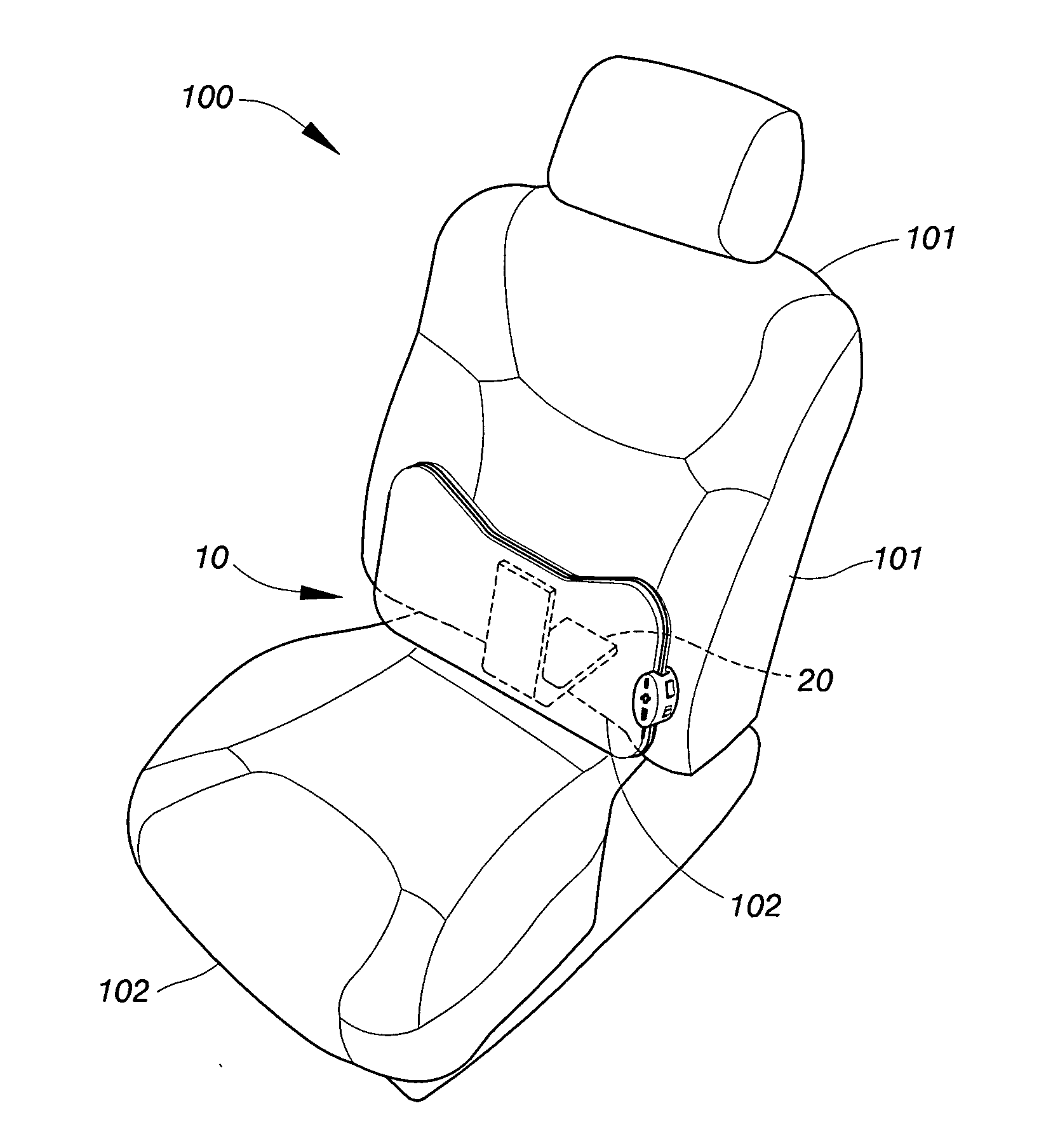
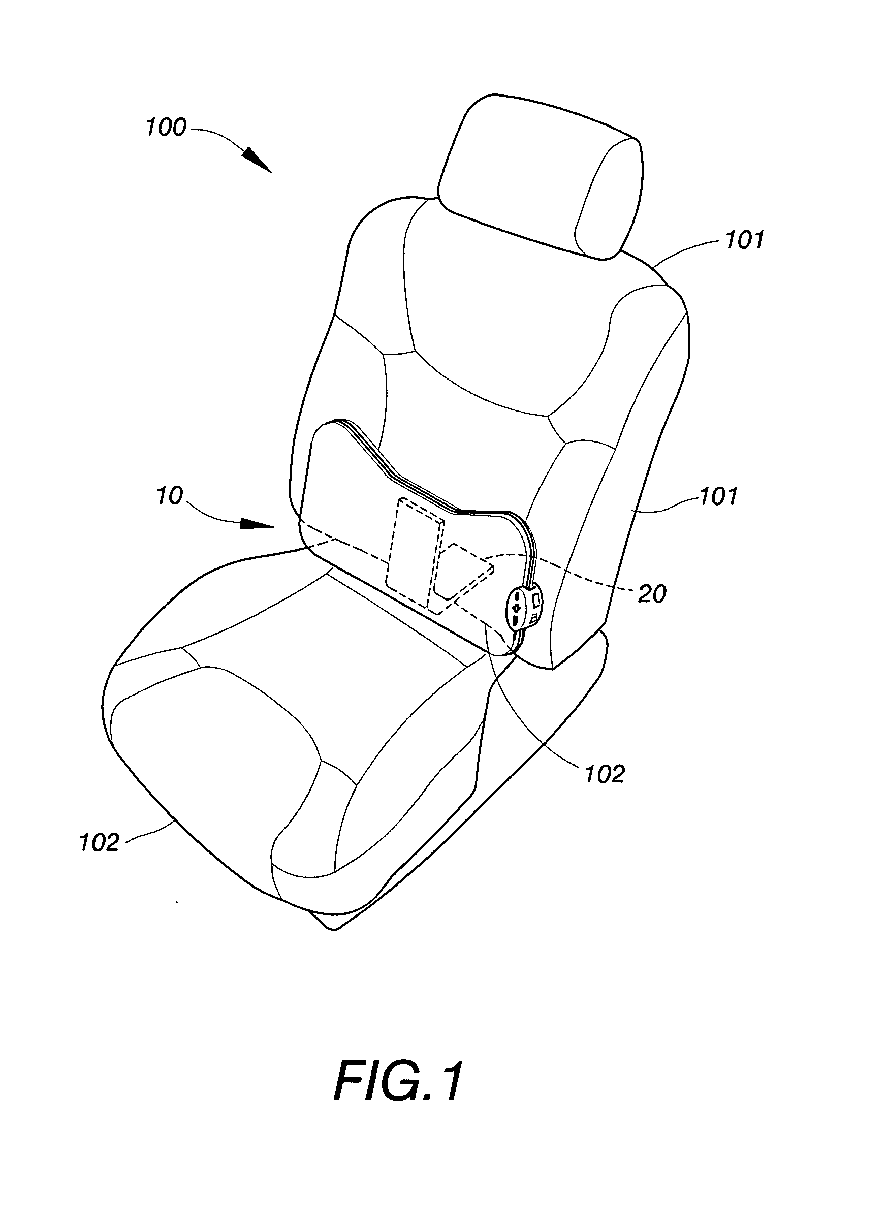
[0033]Referring firstly to FIGS. 1-3, the backrest structure of the present invention is provided on a pad 10 of it with a back clip 20 which has a connecting part 21 movably connecting the back of this pad 10, and with a fixing portion 22 able to be held on a lazy back of 101 of a chair 100, wherein:

[0034]The pad 10 includes an outer envelopment including two coating layers 12 contained therein with an inner lining material 11, the coating layers 12 are provided on its back with a receiving opening 13 which can allow insertion of the back clip 20 in a closely fitting mode.

[0035]The connecting part 21 of the back clip 20 is received in the receiving opening 13 by insertion, and is movably provided in the receiving opening 13, in order that the back clip 20 can have the position of it relatively to that of the pad adjusted by means of the connecting part 21.

[0036]In practicing, as shown in FIGS. 3 to 5, the appearance of the connecting part 21 can be generally a planar board, the con...


PUM


Abstract

A backrest structure including a pad and a back clip, the back clip has a connecting part and a fixing portion to be held on a lazy back of a chair, when the pad is placed on the chair, the fixing portion can be inserted in a seam of the chair or can be clung on the upper area of the rear side of the chair lazy back, so that an effect of having the pad fixed on the chair can be attained; moreover, the relative position of the pad to the back clip can be adjusted; the pad is provided therein with a heat emitting element, a heat sinking element or an air bag, in order to adjust the temperature of the pad or the thickness of the pad for supporting a user, so that the pad can have multiple functions.

Description

BACKGROUND OF THE INVENTION[0001]1. Field of the Invention[0002]The present invention relates to a backrest structure for a chair, and especially to a backrest structure of which a pad is adjustable of its position in relation to the chair.[0003]2. Description of the Prior Art[0004]Following improvement of life quality, modern people think more and more highly of the details concerning their lives. For instance, when one seats on a chair, particularly on a sofa, normally he may have the chair provided with a pad for getting more comfortable feeling of seating; the pad can afford leaning of the waist of a user thereon and make him feel better in seating.[0005]Although the above pad can help a user to get more comfortable feeling of seating, in using the pad, quite many problems are to be solved. For example, the pad can only be placed randomly on a seating cushion, but is unable to have its height adjusted according to requirement of the user; every user has his own size of body conc...

Claims


Application Information

Patent Timeline
IPC IPC(8): A47C7/42A47C31/00A47C7/74A47C7/40
CPCA47C7/402A47C7/467A47C7/425
Inventor CHENG, CHIEN-CHUAN
Owner NITRING ENTERPRISE
Why Eureka
Try Eureka