
Hollow yarn film filtering apparatus

a filtering apparatus and hollow fiber technology, applied in the field of hollow fiber membrane filtering equipment, can solve the problems of large footprint and increase costs, and achieve the effects of reducing the size and cost of filtration facilities, and efficiently increasing the washing effect of hollow fiber filtration membrane modules

Inactive Publication Date: 2011-06-09
ASAHI KASEI CHEM CORP
View PDF4 Cites 2 Cited by
  • Summary
  • Abstract
  • Description
  • Claims
  • Application Information

AI Technical Summary

Benefits of technology

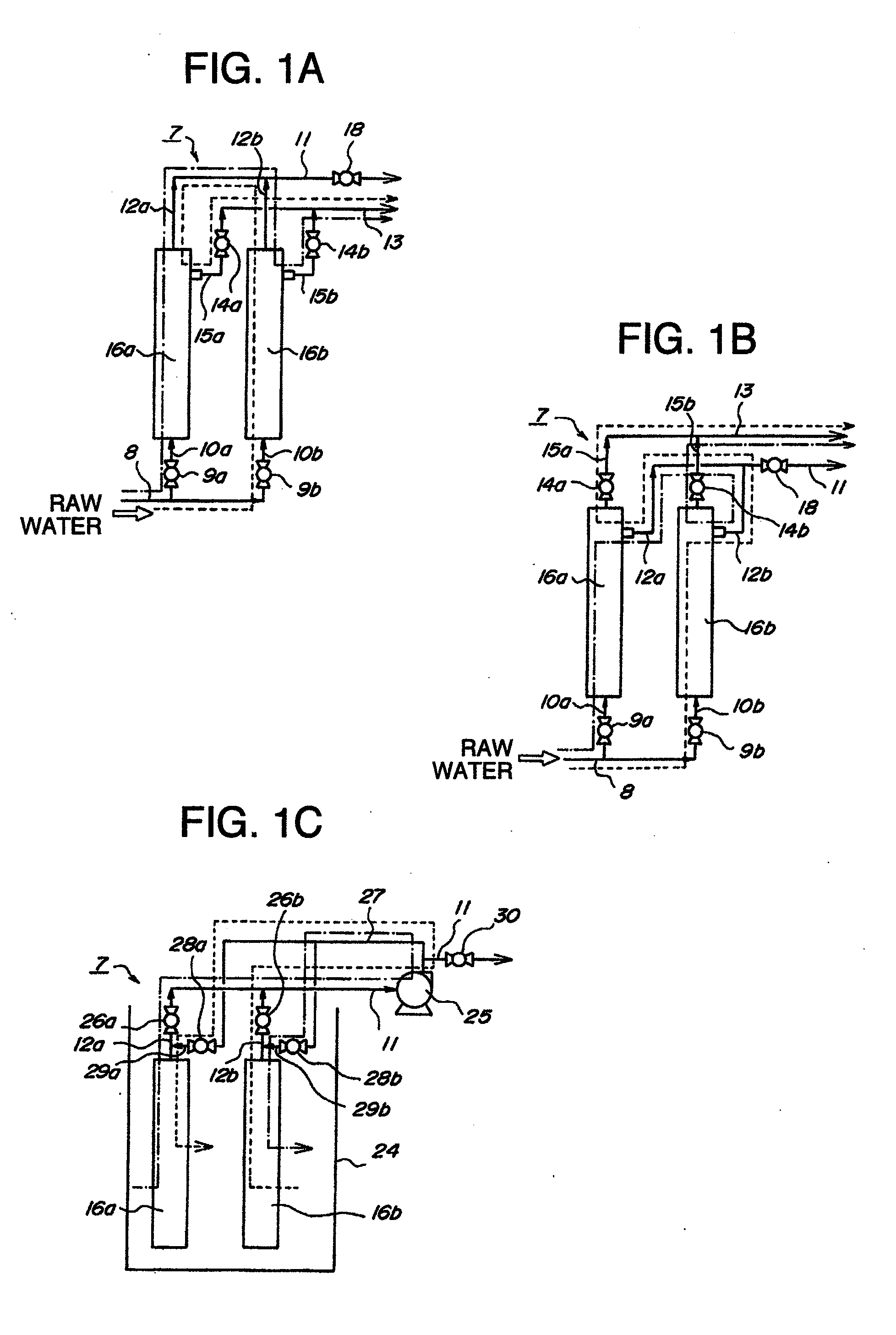
[0013]With the first configuration of the filtration equipment of hollow fiber membrane according to the present invention, the on-off operations of the on-off valves allow the mutual backwash between the plurality of hollow fiber filtration membrane modules, thereby eliminating the need for a wash pump or a backwash tank for washing off suspended matter adhering to a hollow fiber membrane, and reducing the size and cost of a filtration facility.
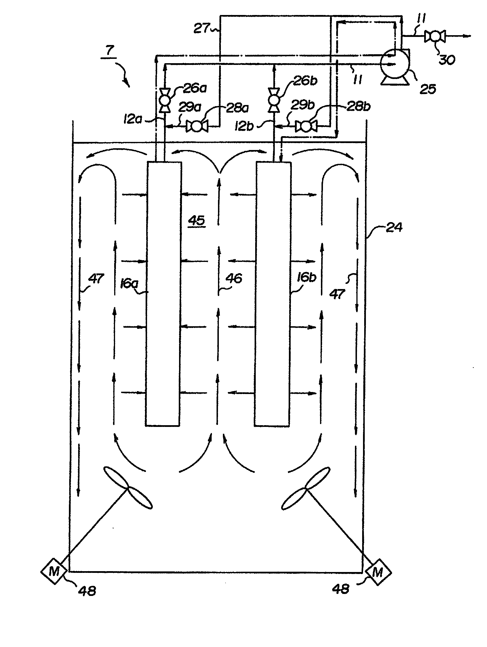
[0014]With the second configuration of the filtration equipment of hollow fiber membrane according to the present invention, during the mutual backwash between the plurality of hollow fiber filtration membrane modules immersed in the treatment tank, the aeration amount control means can increase the amount of air aeration to produce an ascending flow in a treatment liquid in the treatment tank, and thus suspended matter removed from a hollow fiber membrane during backwash is raised by the ascending flow to around a liquid level in the treatment tank. As a result, the ascending flow does not make the suspended matter adhere to a hollow fiber membrane during filtration.
[0015]With the third configuration of the filtration equipment of hollow fiber membrane according to the present invention, the aeration amount control means can increase the amount of air aeration entirely for the hollow fiber membrane during backwash and the hollow fiber membrane during filtration, thereby increasing a washing effect of the hollow fiber filtration membrane module during backwash and a re-adhesion preventing effect of suspended matter to the hollow fiber filtration membrane module during filtration.
[0016]With the fourth configuration of the filtration equipment of hollow fiber membrane according to the present invention, the aeration amount control means can increase the amount of air aeration only for the hollow fiber membrane during backwash to produce an ascending flow for the hollow fiber filtration membrane module during backwash. Thus, suspended matter removed from the hollow fiber filtration membrane module during backwash is retracted by the ascending flow to around the liquid level in the treatment tank to further produce a descending flow along the adjacent hollow fiber filtration membrane module during filtration and produce a swirling flow in the treatment tank, thereby efficiently increasing a washing effect of the hollow fiber filtration membrane module during backwash and a re-adhesion preventing effect of suspended matter to the hollow fiber filtration membrane module during filtration.
[0017]With the fifth configuration of the filtration equipment of hollow fiber membrane according to the present invention, the aeration amount control means can increase the amount of air aeration for the area formed between the hollow fiber membrane during backwash and the hollow fiber membrane during filtration to produce a stable swirling flow, thereby efficiently increasing a washing effect.

Problems solved by technology

However, the above described conventional example requires a wash pump or a backwash tank for washing off suspended matter or the like adhering to a hollow fiber filtration membrane, which has a large footprint and increases costs.

Method used


Image

  • Hollow yarn film filtering apparatus
  • Hollow yarn film filtering apparatus
  • Hollow yarn film filtering apparatus

Examples


Embodiment Construction

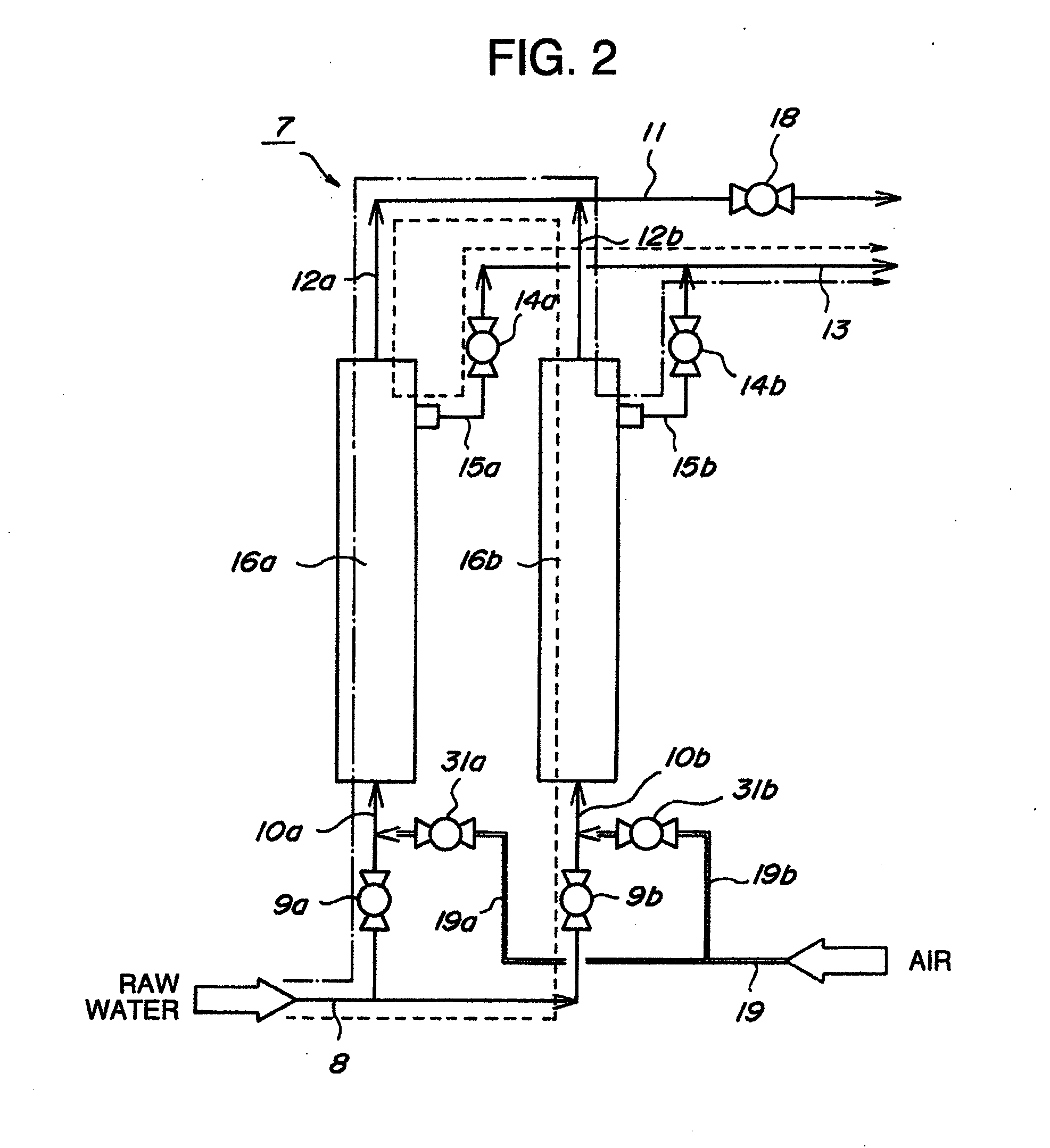
[0028]An embodiment of a filtration equipment of hollow fiber membrane according to the present invention will be described in detail with reference to the drawings. FIG. 1A to FIG. 1C show mutual backwash between a plurality of hollow fiber filtration membrane modules by on-off operations of on-off valves of the filtration equipment of hollow fiber membrane, and FIG. 1A shows a case of an external pressure type, FIG. 1B shows a case of an internal pressure type, and FIG. 1C shows a case of immersed membranes, and FIG. 2 shows a configuration including air supply means for supplying air during the mutual backwash between the plurality of hollow fiber filtration membrane modules in the case of the external pressure type.

[0029]FIG. 1A to FIG. 1C show mutual backwash between a pair of hollow fiber filtration membrane modules 16a and 16b by on-off operations of on-off valves of a filtration equipment of hollow fiber membrane 7, FIG. 1A shows mutual backwash between membranes in a case o...


PUM


Abstract

A filtration equipment of hollow fiber membrane of external pressure type in which pressure is applied to raw liquid from outside of hollow fiber membranes housed in a casing to cause filtrate to pass inside the hollow fiber membranes is provided. The filtration equipment may include a pair of hollow fiber filtration membrane modules in which raw liquid supply channels are connected to a shared raw liquid supply header pipe via on-off valves, filtrate discharge channels which are connected to a shared filtrate discharge header pipe having an on-off valve, and return raw liquid channels which are connected to a shared return raw liquid header pipe via on-off valves, wherein on-off operations of the on-off valves allow mutual backwash between the pair of hollow fiber filtration membrane modules.

Description

CROSS REFERENCE RELATED TO APPLICATION[0001]The present application is a continuation of pending U.S. application Ser. No. 12 / 672,080 filed on Feb. 4, 2010, which is a U.S. National Stage Application under 35 U.S.C. §371 of PCT / JP2008 / 066300, which claims priority to Japanese Application No. 2007-240680 filed Sep. 18, 2007, and Japanese Application No. 2008-152372 filed Jun. 11, 2008, the disclosures of which are expressly incorporated herein by reference in their entirety.TECHNICAL FIELD[0002]The present invention relates to a filtration equipment of hollow fiber membrane (i.e. hollow yarn film filtering apparatus), which allows mutual backwash between hollow fiber filtration membrane modules.BACKGROUND ART[0003]JP-A-9-220446 (Patent Document 1) describes backwash by an external pressure type hollow fiber membrane module as a conventional filtration equipment of hollow fiber membrane.[0004][Patent Document 1] JP-A-9-220446[0005]However, the above described conventional example requ...

Claims


Application Information

Patent Timeline
Patent Type & Authority Applications(United States)
IPC IPC(8): B01D63/02
CPCB01D63/04B01D65/02B01D2313/12B01D2313/18C02F1/444B01D2315/06B01D2317/04B01D2321/04B01D2321/185B01D2313/48B01D69/08B01D2321/2041
Inventor NEJIGAKI, TATSUOHASHIMOTO, TOMOTAKA
Owner ASAHI KASEI CHEM CORP
Learn More