
Water Closet Flange Seal

a technology for flange seals and water closets, applied in water installations, metal working devices, manufacturing tools, etc., can solve the problem of not sealing the impermeable layer to the floor membran

Inactive Publication Date: 2011-06-09
CULNAT
View PDF22 Cites 20 Cited by
  • Summary
  • Abstract
  • Description
  • Claims
  • Application Information

AI Technical Summary

Benefits of technology

The present invention provides improved watertight closet flanges for use in flooring systems. The flanges are designed to prevent water leakage through the flanges and to provide a better seal. The flanges can be installed using a telescopic connection between a drain pipe and the flange, with a sealant dam to prevent sealant from entering the floor. The flanges can be clamped to the floor using a clamping ring and a sealing material. The invention also includes a two-part closet flange design with a cylindrical hub and an annular flange for connection to a drain pipe. Overall, the invention provides improved watertight closet flanges for better protection and prevention of water leakage.

Problems solved by technology

However, such an impermeable layer is not sealed to the floor membrane.
This is a particular problem in a tiled floor, having recessed areas caused by grout lines.

Method used


Image

  • Water Closet Flange Seal
  • Water Closet Flange Seal
  • Water Closet Flange Seal

Examples


Embodiment Construction

[0038]Referring now to the drawings, in which like numerals refer to like components or steps, there are disclosed broad aspects of various exemplary embodiments.

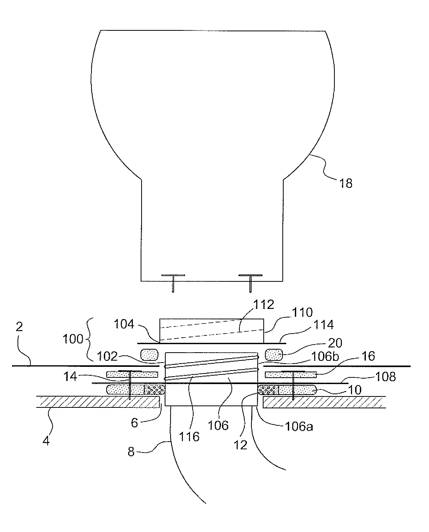
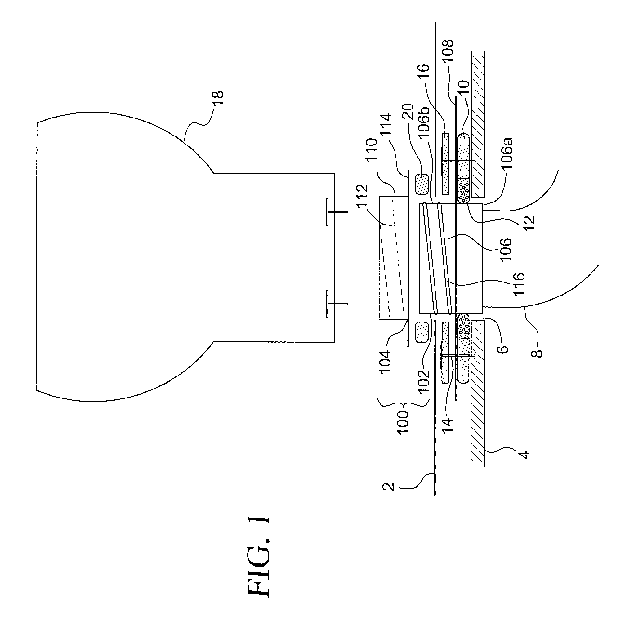
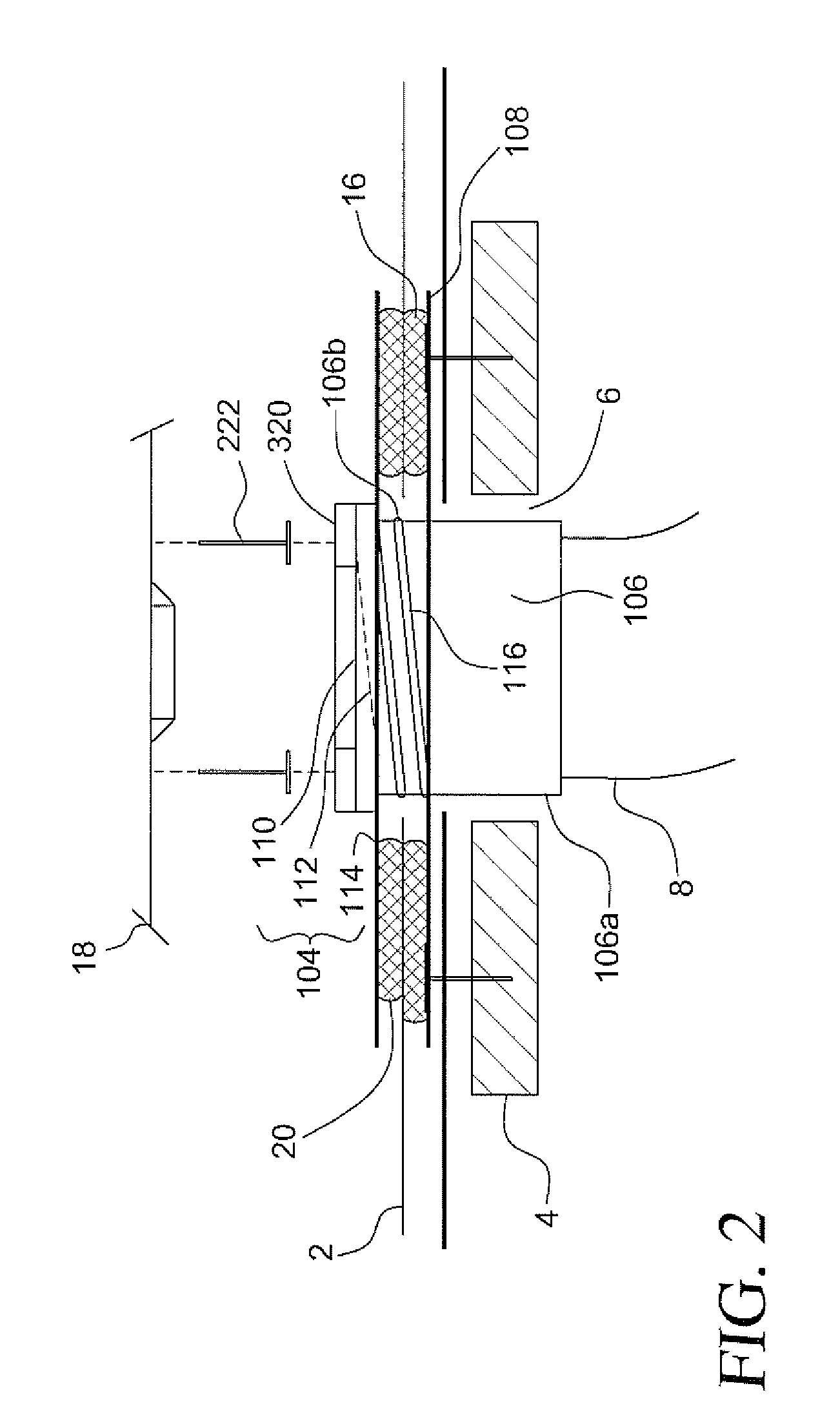
[0039]As seen in FIG. 1, an improved seal between a floor and a closet flange may be accomplished with a two-part closet flange 100, comprising a base portion 102 and a clamping ring 104. An impermeable floor covering 2, such as an impermeable sheet or template, is placed directly over the subfloor, decking, or floor base 4, where the subfloor, decking, or floor base 4 may be made of wood, metal, or concrete. In new construction, the impermeable floor covering 2 is adhered to the base portion 102 of the closet flange 100. The base portion 102 of closet flange 100 has a hub 106 and an annular base flange 108 extending from the hub. The hub 106 is placed through a hole 6 in the subfloor 4, allowing a toilet drain pipe 8 to extend through hole 6 in subfloor 4. The inner surface of a lower cylindrical portion 106a of hub 106 is...


PUM

PropertyMeasurementUnit
heightaaaaaaaaaa
outer diameteraaaaaaaaaa

Abstract

An improved method of installing a closet flange allows installation of plumbing fixtures with a reduced likelihood of leaks. The method involves telescopically fitting an inner or outer surface of a drainpipe to a surface of a cylindrical portion of a hub of a closet flange, where the hub has a base flange extending therefrom; and securing the base flange against the upper surface of a subfloor. A first layer of sealant is applied to an upper surface of the base flange; and a flooring membrane is secured to the upper surface of the base flange by the first layer of sealant. A second layer of sealant is applied to an upper surface of the flooring membrane; and the upper surface of the flooring membrane is clamped between the base flange and a clamping ring. The method may be performed using a two-part closet flange for connection to a drain pipe for a toilet. The two-part closet flange comprises a cylindrical hub adapted to telescopically connect to the drain pipe; an annular flange radially extending from the cylindrical hub; a clamping ring; and a means to clamp a flooring membrane between the clamping ring and the annular flange.

Description

CROSS-REFERENCE TO RELATED APPLICATIONS[0001]This application claims the benefit of U.S. Provisional Application No. 61 / 166,412, filed on Dec. 8, 2009, and U.S. Provisional Application No. 61 / 294,648, filed on Jan. 13, 2010, the entire disclosures of which are incorporated herein by reference.BACKGROUND[0002]1. Field of the Invention[0003]The present application relates to improved seals for water closets.[0004]2. Description of Related Art[0005]In plumbing, a closet flange is a pipe fitting (specifically, a type of flange) that both mounts a toilet to the floor and connects the toilet drain to a drain pipe. The name comes from the term “water closet”, the traditional name for a toilet. A typical closet flange is composed of an ABS, PVC, or metal hub with a round steel mounting flange attached to the top. Other styles are made from copper, brass, stainless steel, or a plastic material.[0006]In a typical installation, the closet flange is mounted on top of the floor with the hub fuse...

Claims


Application Information

Patent Timeline
Patent Type & Authority Applications(United States)
IPC IPC(8): E03D11/16B23P17/04
CPCY10T29/49826E03D11/16E03D11/10E03D11/135
Inventor CULWELL, BILL
Owner CULNAT
Learn More