
Method and apparatus for detecting command wire utilized to detonate an improvised explosive device (IED)

a technology of improvised explosive devices and command wires, which is applied in the field of system for detecting command wires, can solve the problems of not readily observable explosives or command wires, and the use of common command wires is more difficult to detect,

Inactive Publication Date: 2011-06-02
BAE SYST INFORMATION & ELECTRONICS SYST INTERGRATION INC
View PDF6 Cites 2 Cited by
  • Summary
  • Abstract
  • Description
  • Claims
  • Application Information

AI Technical Summary

Benefits of technology

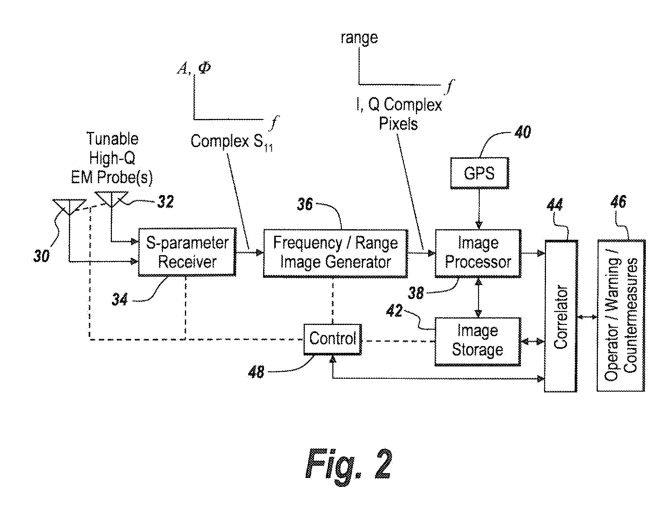
[0021]It is noted that there will be peaks in amplitude at given ranges. There will also be phase peaks in terms of the phase function for the difference in phase between the outgoing signal and the reflected signal. Note that the progression of the phase will be different for different frequencies, different resonances and different ranges. It has thus been found that phase is a function of range for different frequencies, enabling one to template out the effect.

Problems solved by technology

Deployed forces face an increasing number of threats from their adversaries.
While remote detonation methods include radio frequency, infrared and hydraulic actuators, by far the more difficult to detect is the use of the common command wire.
Thus, convoys have routinely been attacked by improvised explosive devices which are buried and camouflaged so that neither the explosive nor the command wire is readily observable.
However, the use of wires to detonate explosives from for instance distances of 100 to 500 feet provide a stealth component to IED detonation because the wires themselves are very thin and easily hidden or buried.
Since microwave UHF signals and VHF signals cannot effectively penetrate into the infrastructures of the city or below ground, one has to investigate what near field approaches can be applied that operate in a frequency range which will in fact penetrate local objects in the ground.

Method used


Image

  • Method and apparatus for detecting command wire utilized to detonate an improvised explosive device (IED)
  • Method and apparatus for detecting command wire utilized to detonate an improvised explosive device (IED)
  • Method and apparatus for detecting command wire utilized to detonate an improvised explosive device (IED)

Examples


Embodiment Construction

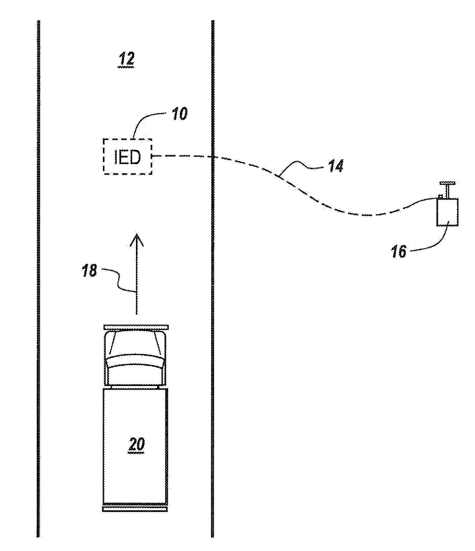
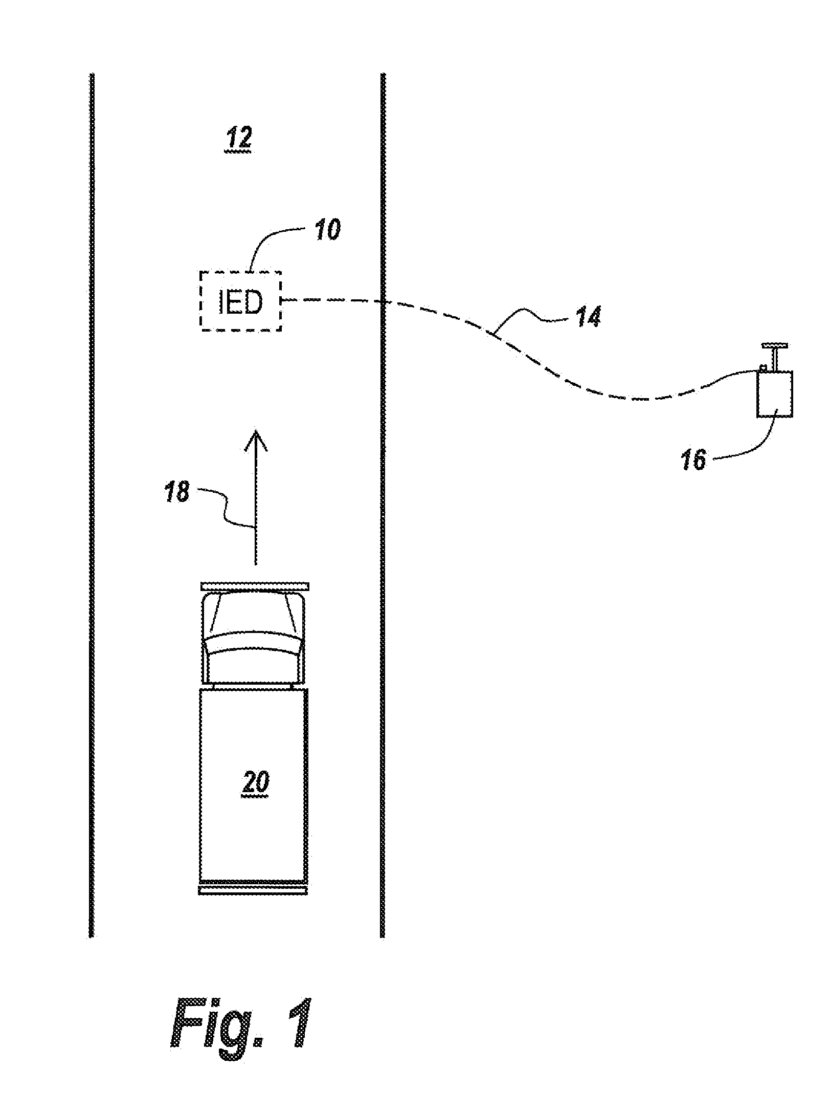
[0044]Referring now to FIG. 1, an improvised explosive device 10 is placed beneath a road 12 and is activated by a command wire 14 coupled to a detonator 16 in the form of a conventional plunger assembly.

[0045]IED 10 is placed along the direction of travel 18 of a vehicle 20, with the purpose of the stealth IED and command wire being to surprise the vehicle and then blow it up.

[0046]It is the purpose of the subject invention to detect such stealth devices to permit countermeasuring.

[0047]In order to provide for early enough warning of the existence of a command wire in one embodiment, as illustrated in FIG. 2, a pair of tunable high Q electromagnetic probes 30 and 32, in one embodiment in the form of HF coil antennas, are coupled to an S-parameter receiver 34, the output of which is the unitless complex reflection coefficient S-11, namely involving amplitude, phase and frequency. The heart of the S parameter receiver is a network analyzer. Either S11 or S12 modes may be used. S11 re...


PUM


Abstract

A method and apparatus is devised for detecting command wires utilized to detonate an improvised explosive device or other objects of interest in which frequency-scanned RF in the HF region of the electromagnetic spectrum is projected out across a given area and returns are detected and converted into image data in which phase, amplitude, range and frequency associated with the incoming data is correlated with frequency-dependent range templates to determine the existence of, the range of and the direction of command wires or other objects of interest.

Description

FIELD OF THE INVENTION[0001]This invention relates to a system for detecting command wires that are used to activate explosives and more particularly to resonance sensing and the utilization of range templates to detect the existence of and the range to command wires utilized for the firing of Improvised Explosive Devices.BACKGROUND OF THE INVENTION[0002]Deployed forces face an increasing number of threats from their adversaries. Of chief concern is the Improvised Explosive Device (IED). IEDs are generally hidden near or underneath roadways and remotely detonated by an operator stationed nearby. While remote detonation methods include radio frequency, infrared and hydraulic actuators, by far the more difficult to detect is the use of the common command wire.[0003]The command wires are typically embedded in the ground where they can neither be seen or readily detected. Thus, convoys have routinely been attacked by improvised explosive devices which are buried and camouflaged so that ...

Claims


Application Information

Patent Timeline
IPC IPC(8): G08B21/00
CPCG01V3/12F41H11/136
Inventor APOSTOLOS, JOHN T.MILLARD, RICHARD J.
Owner BAE SYST INFORMATION & ELECTRONICS SYST INTERGRATION INC
Learn More