Item Securing Hook Assembly

a technology for items and hooks, which is applied in the field of item securing hooks or units, can solve the problems of “push, drop and grab” theft of items operatively stored on hooks, and is difficult for thieves to remove from over-the-stall attempts, and achieves the effect of quick and blind maneuvering by thieves

Active Publication Date: 2011-06-02
PORTZ THOMAS J
View PDF60 Cites 0 Cited by
  • Summary
  • Abstract
  • Description
  • Claims
  • Application Information

AI Technical Summary

Benefits of technology

[0010]Preferred embodiments of the present invention, because they have no moving parts, offer durability, cost effectiveness, and simplicity. One such preferred embodiment includes a mounting plate for attachment to a wall, door or the like. The mounting plate includes an upper end and a lower end. The mounting plate can be secured to a surface, such as a restroom stall door or wall, with screws, adhesive or the like. The preferred embodiment further includes a first hook element having a first attachment end and a second distal end, the first hook element extending generally toward the upper end of the mounting plate and away from the mounting plate. In addition, the unit includes a securing member extending from the second end of the first hook element in the direction towards the mounting plate and a second hook element having an outer end, the second hook element positioned above the first hook element and extending away from the mounting plate. The preferred hook is arranged and configured such that the securing member of the first hook element is in the same horizontal plane as the outer end of the second retaining member when the hook is operatively secured to the surface. This configuration provides for a hook requiring a generally “Z”-shaped or zigzag motion to remove articles from within a storage area of the hook, thus making “push, drop and grab” theft of an item operatively stored on the hook extraordinarily difficult.
[0011]Alternate preferred embodiments of the present invention also include a mounting plate having upper and lower ends. In preferred embodiments, the hook assembly includes a first hook element extending from the lower end of the mounting plate. The first hook element includes a first attachment end and a second distal end. The first attachment end is interconnected to the mounting plate and the second distal end preferably includes a securing member extending toward the mounting plate. In preferred embodiments, the securing member is generally perpendicular to the mounting plate such that articles stored in a receiving area of the hook assembly are easy to place on the hook element, yet difficult for thieves to remove from an over-the-stall attempt as the securing member would have to be quickly and blindly maneuvered by the thief. Additional embodiments can include an upper securing member extending from the upper end of the mounting plate. The upper securing member preferably includes a first member that extends over the lower hook element when the hook assembly is operatively secured to the vertical surface. The upper member further includes a second member that extends downwardly from the first member and below the lower hook element. Preferably, the second member further includes a crook that at least partially extends towards the mounting plate such that it is at least partially in the same horizontal plane as the lower hook element.

Problems solved by technology

This configuration provides for a hook requiring a generally “Z”-shaped or zigzag motion to remove articles from within a storage area of the hook, thus making “push, drop and grab” theft of an item operatively stored on the hook extraordinarily difficult.
In preferred embodiments, the securing member is generally perpendicular to the mounting plate such that articles stored in a receiving area of the hook assembly are easy to place on the hook element, yet difficult for thieves to remove from an over-the-stall attempt as the securing member would have to be quickly and blindly maneuvered by the thief.

Method used


Image

  • Item Securing Hook Assembly
  • Item Securing Hook Assembly
  • Item Securing Hook Assembly

Examples


Embodiment Construction

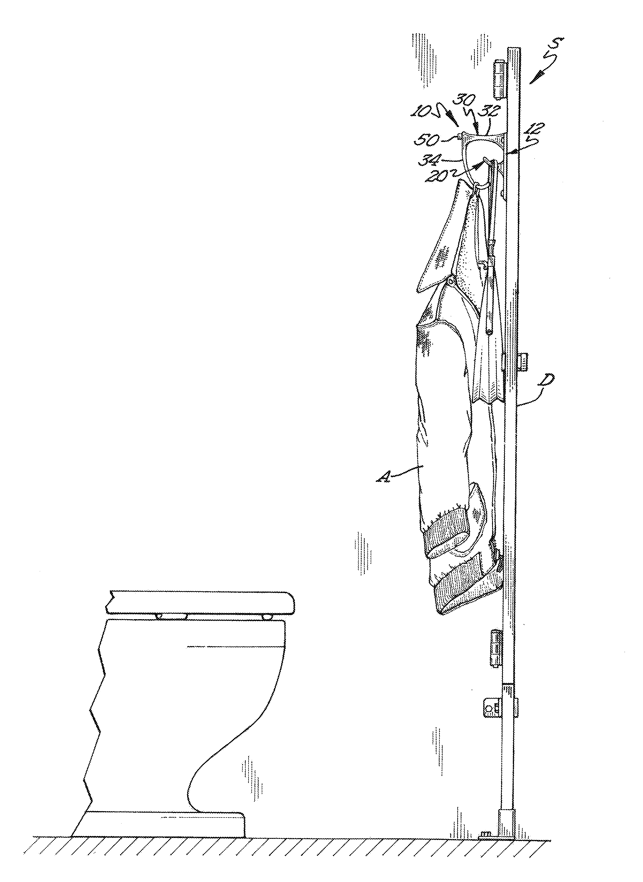
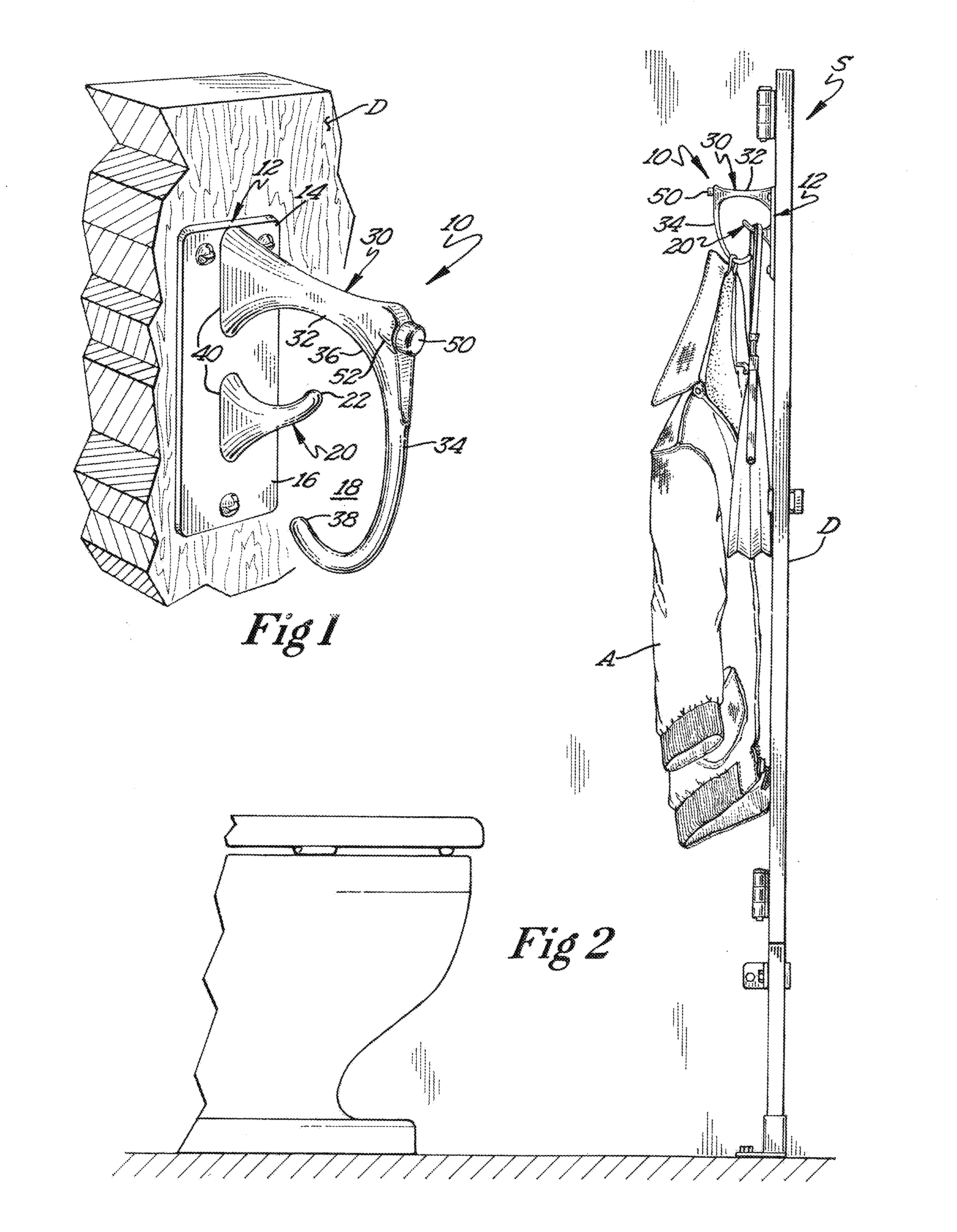
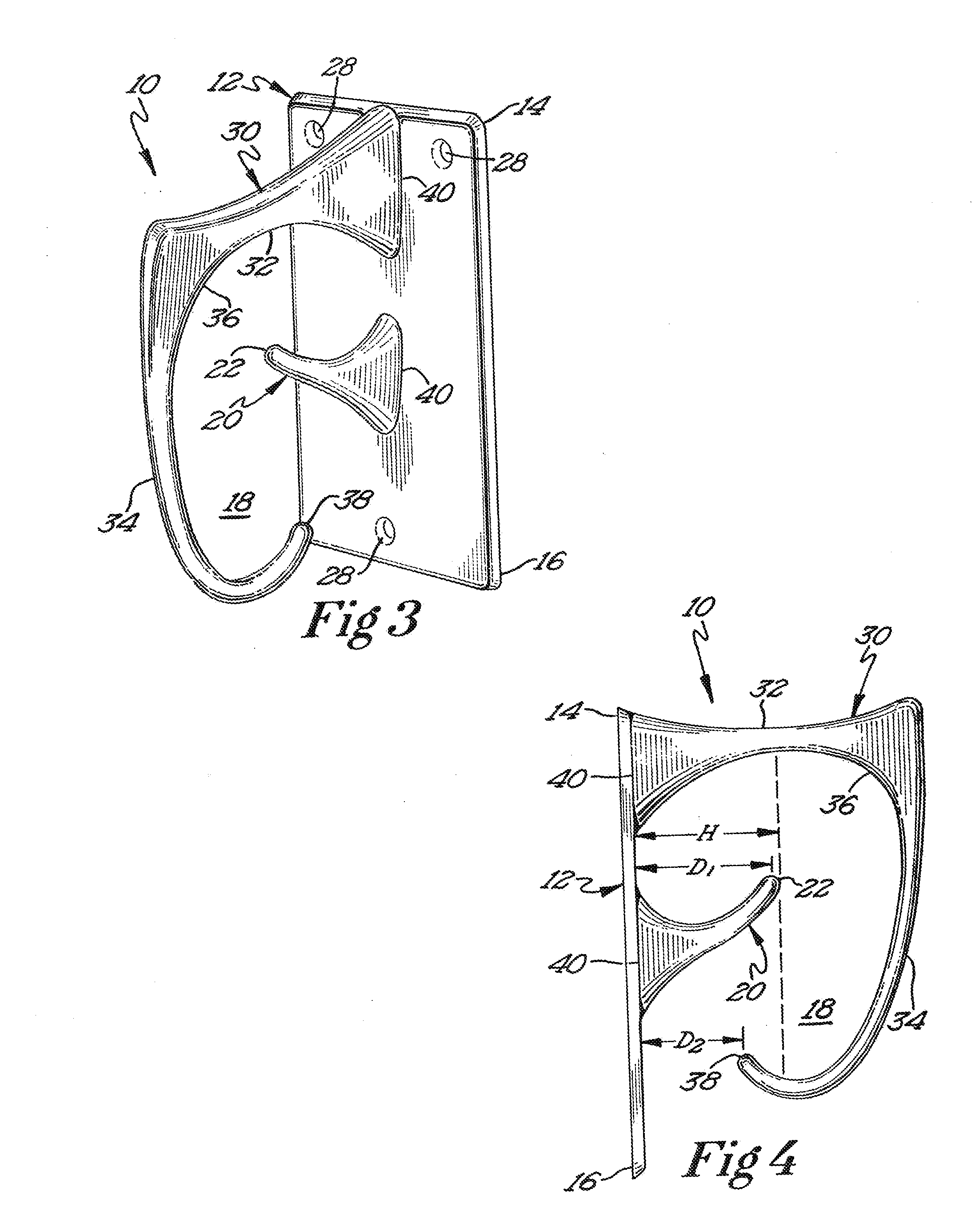
[0026]Illustrative embodiments are illustrated in FIGS. 1-12. One preferred embodiment of a hook assembly 10 or unit is illustrated in FIGS. 1-4. The illustrated unit or hook assembly 10 includes a mounting plate 12 arranged and configured for mounting on a vertical surface, such as a wall or restroom stall door D, the mounting plate 12 having an upper end 14 and a lower end 16. Extending from the mounting plate 12 is a lower hook element 20 having a lower crook 22 on which articles A can be hung. The preferred hook assembly 10 further includes an upper hook element 30 including a first member 32 extending outwardly and possibly upwardly from the mounting plate and a second member 34 extending downwardly from the first member 32. Preferably, the second member 34 extends below the lower hook element 20 such that articles A secured on the lower hook element 20 and within a receiving area 18 are thoroughly secured. In further preferred embodiments, the second member 34 includes an uppe...


PUM


Abstract

Units or hook assemblies arranged and configured to adequately capture and hold personal items which have some type of handle, rope, strap or the like. Preferred embodiments include a mounting plate for attachment to a restroom stall wall, door or the like. The mounting plate includes an upper end and a lower end. Preferred embodiments further include a first and second hook elements extending outwardly from the mounting plate. Preferred embodiments are arranged and configured to hinder theft of personal items stored on the hook from an over the stall door or wall attempt.

Description

RELATED APPLICATIONS[0001]This application is a continuation of co-pending U.S. patent application Ser. No. 12 / 171,722, filed on Jul. 11, 2008, the disclosure of which is herein incorporated by reference.BACKGROUND[0002]1. Field of the Invention[0003]The present invention relates generally to a hook assembly or unit for attachment to a vertical surface. Particularly, the present invention relates to a unit attachable to a restroom stall wall or door for temporarily storing personal items such as hats, purses, backpacks, coats and the like. More particularly, the present invention relates to a restroom stall hook assembly that hinders theft of personal items stored in a receiving area of the hook assembly.[0004]2. Description of the Related Art[0005]There are a wide variety of hooks designed for hanging personal items such as hats, purses, backpacks, coats and the like. Many of these hooks are used in public restrooms, often secured to a stall surface such as the stall door or side w...

Claims


Application Information

Patent Timeline
Patent Type & Authority Applications(United States)
IPC IPC(8): F16B45/00
CPCA47G25/0607
Inventor PORTZ, THOMAS J.
Owner PORTZ THOMAS J
Why Eureka
Try Eureka