
Retractable pet leash with self powered electric light

a self-powered, electric light technology, applied in the direction of mechanical drive lighting devices, taming and training devices, other apparatus, etc., can solve the problems of increasing the number of dogs that the housing is a bit bulky, and the canine can be allowed to exercise freely. to achieve the effect of thin profil

Inactive Publication Date: 2011-06-02
MITCHELL LUCY A
View PDF11 Cites 13 Cited by
  • Summary
  • Abstract
  • Description
  • Claims
  • Application Information

AI Technical Summary

Benefits of technology

[0021]It is another object of the present invention to provide a retractable pet leash with an integrated light source which does not require batteries.
[0023]It is yet another object of the present invention to provide a retractable pet leash with an integrated self powered light source and a relatively thin profile.

Problems solved by technology

Locations where pets, particularly dogs, can be allowed to exercise freely are becoming scarce and it is necessary to keep pets leashed at all times, when they are away from their owner's property.
While these devices add a measure of safety, if the retractable leash is religiously maintained on the charging system, the housing is somewhat bulky because of the need to accommodate the batteries and the charging system must remain in continuous operation, in the owner's home.

Method used


Image

  • Retractable pet leash with self powered electric light
  • Retractable pet leash with self powered electric light
  • Retractable pet leash with self powered electric light

Examples


Embodiment Construction

[0034]At the outset, it should be appreciated that like drawing numbers on different drawing views identify identical, or functionally similar, structural elements of the invention. While the present invention is described with respect to what is presently considered to be the preferred aspects, it is to be understood that the invention as claimed is not limited to the disclosed aspects.

[0035]Furthermore, it is understood that this invention is not limited to the particular methodology, materials and modifications described and as such may, of course, vary. It is also understood that the terminology used herein is for the purpose of describing particular aspects only, and is not intended to limit the scope of the present invention, which is limited only by the appended claims.

[0036]Unless defined otherwise, all technical and scientific terms used herein have the same meaning as commonly understood to one of ordinary skill in the art to which this invention belongs. Although any meth...


PUM


Abstract

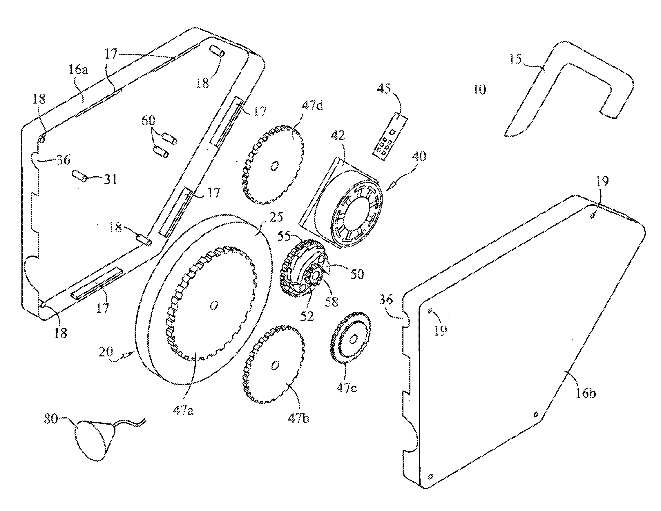
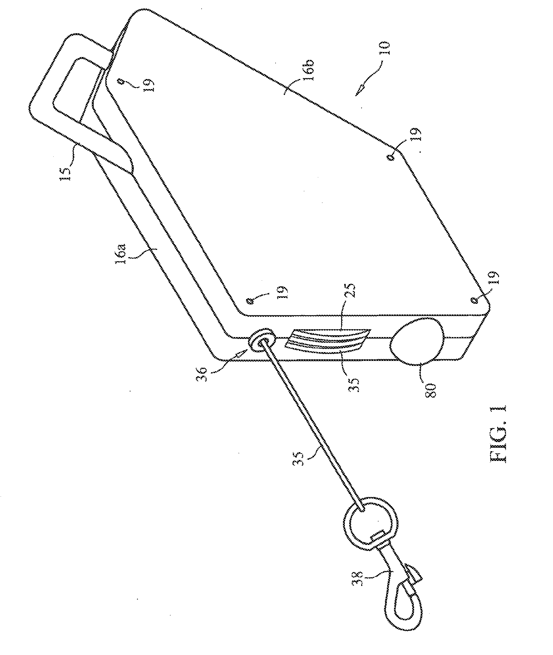
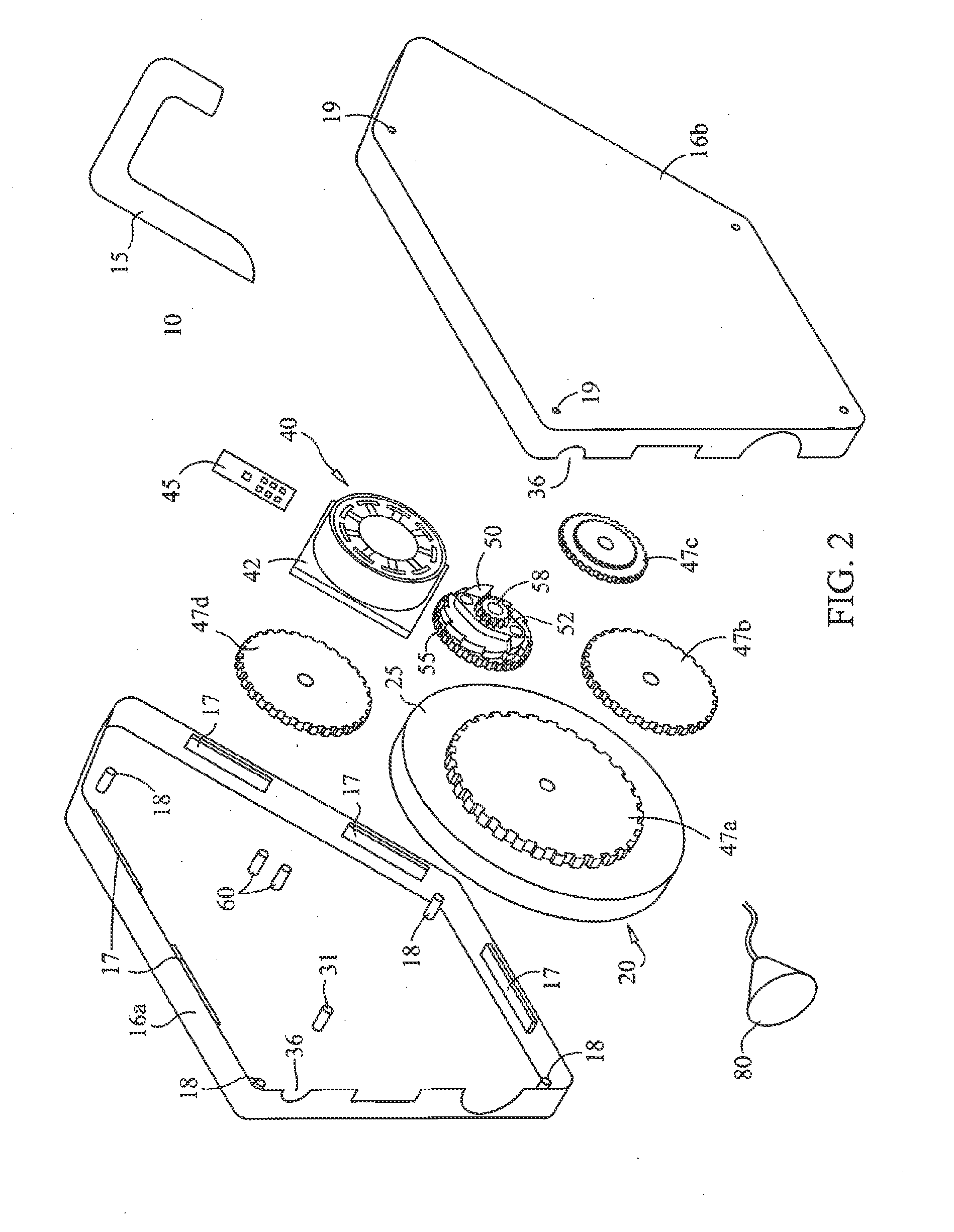
A retractable pet leash having an integrated lamp powered by an electric generator. A spool is rotatably mounted inside a housing and a leash cord is coiled on the spool. The spool rotates in a first direction of rotation as the leash cord pays out through an opening provided in the housing. A spring inside the housing is configured to bias the spool toward rotation opposite the first direction of rotation, for retracting the leash cord. A circular toothed gear is attached to the spool for synchronous rotation and a set of speed change gears are configured to translate rotation of the circular toothed gear to turn the generator. A cup gear, having an inner wall provided with a unidirectional teeth groove, engages a speed change gear. A prism plate with pivotally mounted pawls is rotatably mounted in contact with the unidirectional teeth groove, for translating rotation in one direction only, to the generator. The generator outputs direct current to a circuit board. The circuit board includes a set of capacitors for storing electric potential and an electric filter for outputting a stable power supply to energize the lamp.

Description

CROSS-REFERENCE TO RELATED APPLICATIONS[0001]This application is a Continuation-in-Part of application Ser. No. 11 / 598,386, filed on Nov. 13, 2006, which application is incorporated herein by reference in its entirety.BACKGROUND OF THE INVENTION[0002]1. Field of the Invention[0003]The present invention generally relates to retractable pet leashes, and more particularly, to a retractable pet leash having an integral self powered light source.[0004]2. Description of the Prior Art[0005]As populations increase, more people find themselves living in urban settings. Locations where pets, particularly dogs, can be allowed to exercise freely are becoming scarce and it is necessary to keep pets leashed at all times, when they are away from their owner's property. Some jurisdictions impose regulations requiring the use of a leash for pets. Retractable leashes have become popular because they allow a pet to quickly move to a distance several meters away from the owner but the owner can maintai...

Claims


Application Information

Patent Timeline
Patent Type & Authority Applications(United States)
IPC IPC(8): A01K27/00B65H75/34A01K29/00F21L13/06
CPCA01K27/006A01K27/004
Inventor MITCHELL, LUCY A.
Owner MITCHELL LUCY A
Learn More