
Method of designing dental-implant prosthesis

a technology of dental implants and prostheses, applied in the field of artificial dental implantation, can solve the problems of malocclusion of artificial teeth, failure to accurately acquire digital data of analog, and digital data of bite molds

Inactive Publication Date: 2011-05-26
POU BIOTECH
View PDF9 Cites 17 Cited by
  • Summary
  • Abstract
  • Description
  • Claims
  • Application Information

AI Technical Summary

Benefits of technology

[0006]The primary objective of the present invention is to provide a method of designing a dental-implant prosthesis, which does not need to acquire a solid bite mold from the patient's oral cavity.
[0007]The secondary objective of the present invention is to provide a method of designing a dental-implant prosthesis, which can accurately position the prosthesis to further come up with the most proper formation of the prosthesis after adjustment in such a way the definite information about the dental occlusion can be acquired to enable good occlusion of artificial tooth / teeth installed later.

Problems solved by technology

Because the connection interface of the aforesaid analog is not obvious, scanning the aforesaid bite mold can only come up with digital data of the bite mold and fails to accurately acquire digital data of the analog.
However, it is highly possible to come up with an inaccurate abutment to further affect the combinative relationship that the abutment is positioned in the analog, such that it is failed to design the optimal formation of the abutment.
In this way, no definite information about the dental occlusion is available to possibly cause malocclusion of artificial tooth / teeth installed later, and no definite information about the dental arrangement to lessen the aesthetic appearance of the artificial tooth / teeth after the dental implantation.

Method used


Image

  • Method of designing dental-implant prosthesis
  • Method of designing dental-implant prosthesis
  • Method of designing dental-implant prosthesis

Examples


Embodiment Construction

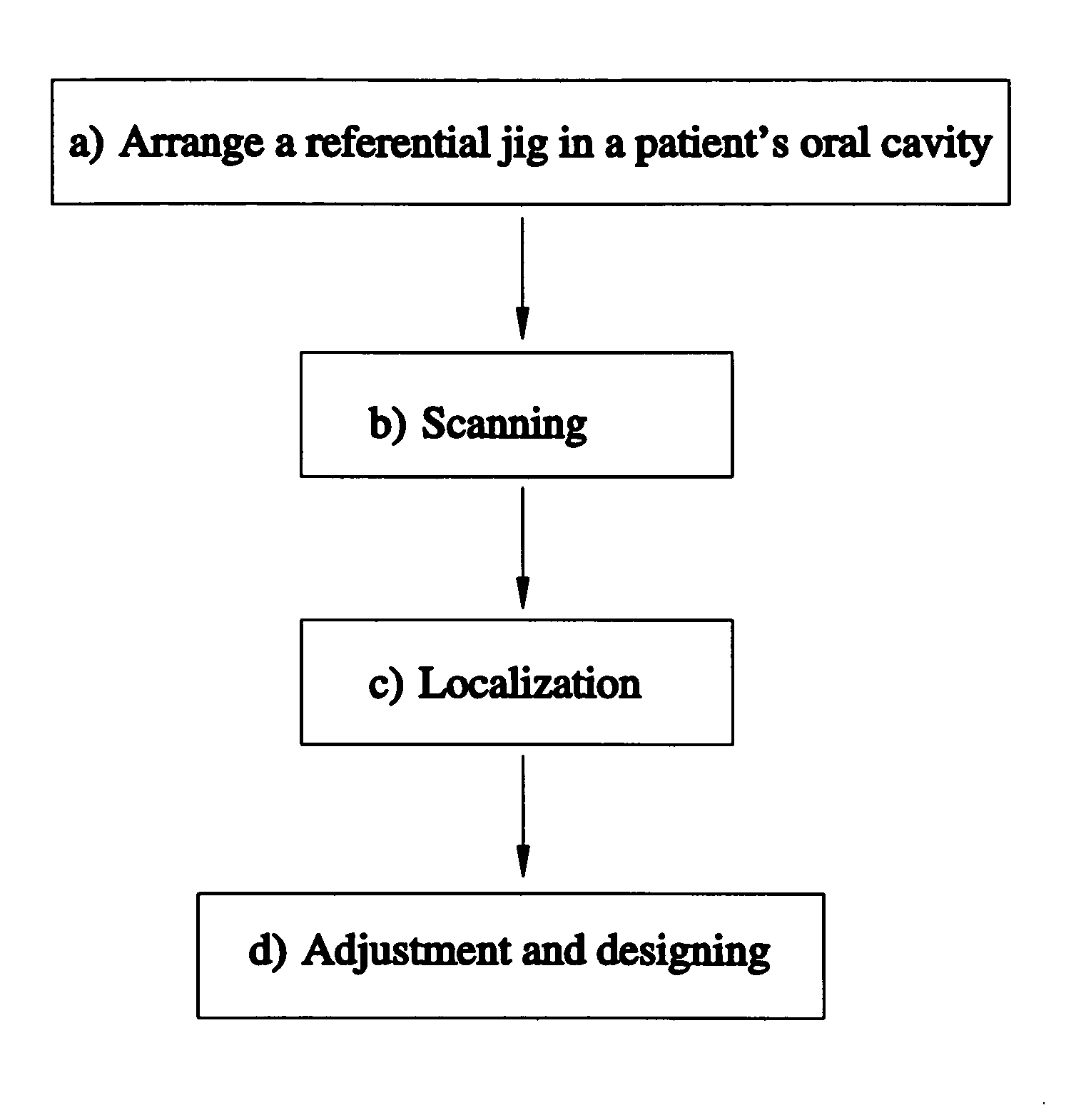
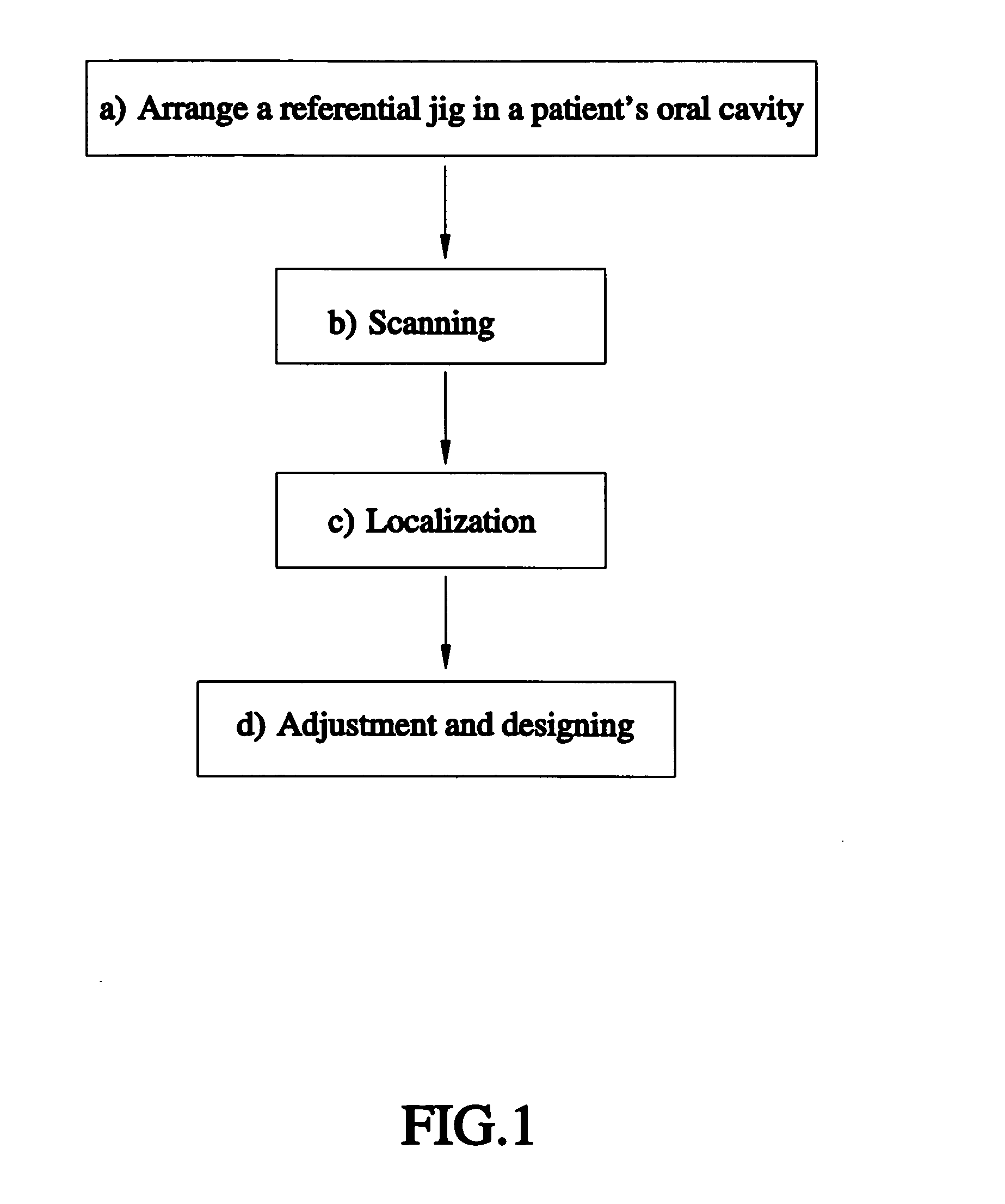
[0027]Referring to FIG. 1, a method of designing a dental-implant prosthesis in accordance with a first preferred embodiment of the present invention includes the following steps.

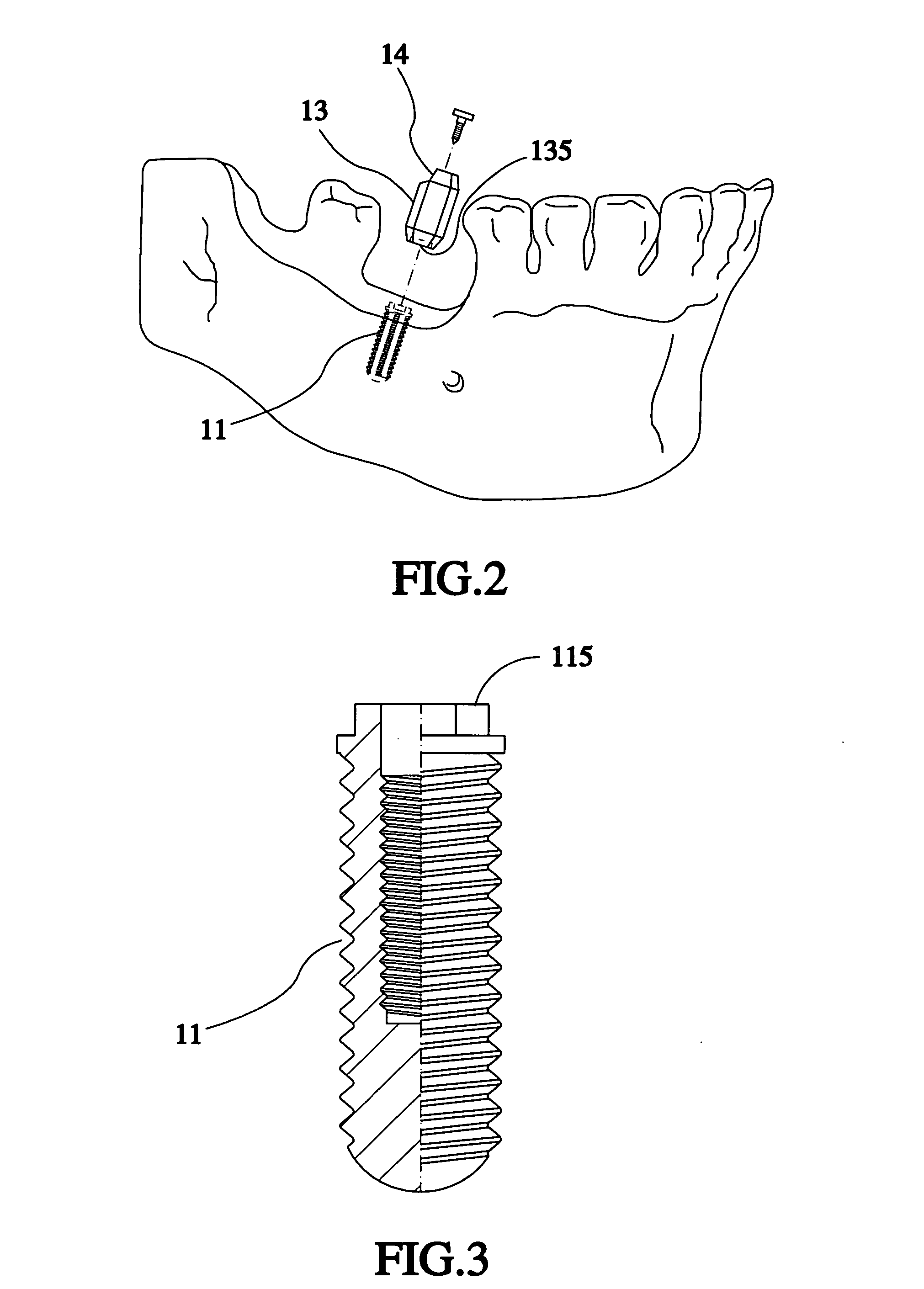
[0028]a) As shown in FIGS. 2-5, under the condition that there is a fixture 11 in a patient's oral cavity, arrange a referential jig 13 corresponding to the fixture 11, and then combine the selected referential jig 13 into the fixture 11. The referential jig 13 includes a plurality of feature points 14 exposed outside the fixture 11 and dental gum in the patient's oral cavity. The fixture 11 includes a connection interface 115 formed at a top side thereof. The referential jig 13 includes an opposite-joint interface 135 formed at a bottom side thereof and corresponding to the connection interface 115. In this way, the referential jig 13 can be combined into the fixture 11 when the connection interface 115 is connected with the opposite-joint interface 135. The feature points 14 are convex or concave or both....


PUM


Abstract

A method of designing a dental-implant prosthesis includes the steps of arranging a referential jig and combining the referential jig into a fixture installed in a patient's oral cavity, the referential jig having at least one feature point, the fixture having a connection interface, the referential jig having an opposite-joint interface; scanning the patient's oral cavity to acquire an oral digital data and a referential-jig digital data having at least one feature-point digital data; selecting one digital dental-implant prosthesis from a prosthetic database in a computer, a digital positioning jig overlapping the digital dental-implant prosthesis for combination with the connection interface, and proceeding with overlapping and localization of the digital positioning jig and the referential jig digital data to combine the referential jig digital data into the connection interface; and adjusting the position, size, and angle of the digital dental-implant prosthesis to acquire the digital dental-implant prosthesis which is most suitable to the patient.

Description

BACKGROUND OF THE INVENTION[0001]1. Field of the Invention[0002]The present invention relates generally to artificial dental implantation, and more particularly, to a method of designing a dental-implant prosthesis.[0003]2. Description of the Related Art[0004]A conventional dental-implant design initially needs to acquire a bite mold from a patient's oral cavity. The bite mold includes at least one analog planted in the patient's bone under simulation. Next, a dental-implant prosthesis, e.g. artificial abutment, is created for combination into the analog. Finally, a dental crown is created and mounted to the dental-implant prosthesis to complete the whole design of the dental implant.[0005]Because the connection interface of the aforesaid analog is not obvious, scanning the aforesaid bite mold can only come up with digital data of the bite mold and fails to accurately acquire digital data of the analog. Besides, the combination of the analog and the abutment is provided with specifi...

Claims


Application Information

Patent Timeline
IPC IPC(8): A61C13/08
CPCA61C8/0001A61C8/005A61C8/006A61C8/0068A61C9/0046A61C8/0096A61C8/0098A61C13/0004A61C8/0077
Inventor YAU, HONG-TZONGKUO, CHUAN-CHUCHEN, JIUN-RENCHEN, CHIEN-ANTSOU, LEE-SEN
Owner POU BIOTECH
Learn More