
Motor interface for parallel drive shafts within an independently rotating member

Active Publication Date: 2011-05-19
INTUITIVE SURGICAL OPERATIONS INC
View PDF44 Cites 347 Cited by
  • Summary
  • Abstract
  • Description
  • Claims
  • Application Information

AI Technical Summary

Benefits of technology

[0010]Mechanisms, assemblies, systems, tools, and methods are provided, many of which incorporate the use of an offset drive shaft within an independently rotating member. Such mechanisms, assemblies, systems, tools, and methods may be particularly beneficial for use in surgery, for example, in minimally invasive surgery, in minimally invasive robotic surgery, as well as other types of surgery. The combination of an offset drive shaft mounted for rotation within an independently rotatable instrument shaft allows significant actuation power to be transferred to an end effector while leaving a central region of the instrument shaft available for routing of other components, for example, control cables, control wires, catheters, or other such components. Drive shaft actuation can be used to articulate and / or orient an end effector, for example, so as to provide a relatively high desired clamping force, such as for cutting or stapling, optionally with a limited response rate. Cable actuation may be used for relatively lower force articulation and / or orientation of the end effector when a higher response rate is desired, such as when telesurgically grasping and manipulating tissues. Exemplary hybrid cable / shaft actuated systems may selectably actuate a single grasping / treatment jaw joint using either a high force shaft drive or a high response cable drive. While the various embodiments disclosed herein are primarily described with regard to surgical applications, related mechanisms, assemblies, systems, tools, and methods may find use in a wide variety of applications, both inside and outside a human body, as well as in non-surgical applications.

Problems solved by technology

Unfortunately, many known surgical devices, including known linear clamping, cutting and stapling devices, often have opposing jaws that may be difficult to maneuver within a patient.
For known devices having opposing jaws that are maneuverable within a patient, such devices may not generate sufficient clamping force for some surgical applications (e.g., tissue clamping, tissue stapling, tissue cutting, etc.), which may reduce the effectiveness of the surgical device.

Method used


Image

  • Motor interface for parallel drive shafts within an independently rotating member
  • Motor interface for parallel drive shafts within an independently rotating member
  • Motor interface for parallel drive shafts within an independently rotating member

Examples


Embodiment Construction

[0054]Mechanisms, assemblies, systems, tools, and methods incorporating the use of an offset drive shaft within an independently rotating member are provided. Such mechanisms, assemblies, systems, tools, and methods may be particularly beneficial for use in surgery, for example, in minimally invasive surgery, minimally invasive robotic surgery, as well as other types of surgery. While the various embodiments disclosed herein are primarily described with regard to surgical applications, related mechanisms, assemblies, systems, tools, and methods can be used in a wide variety of applications, both inside and outside a human body, as well as in non-surgical applications.

[0055]Minimally Invasive Robotic Surgery

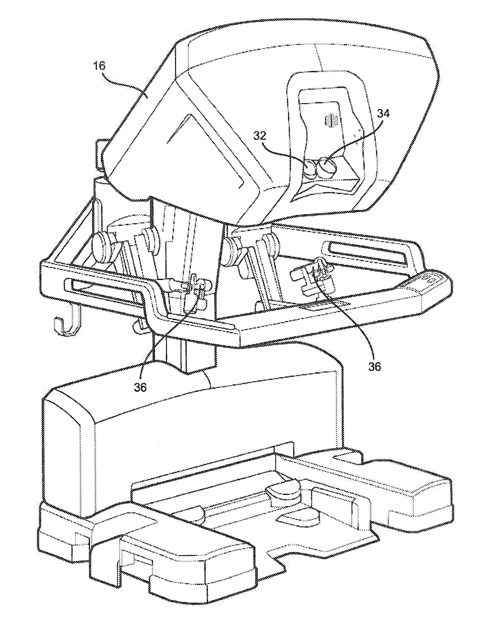
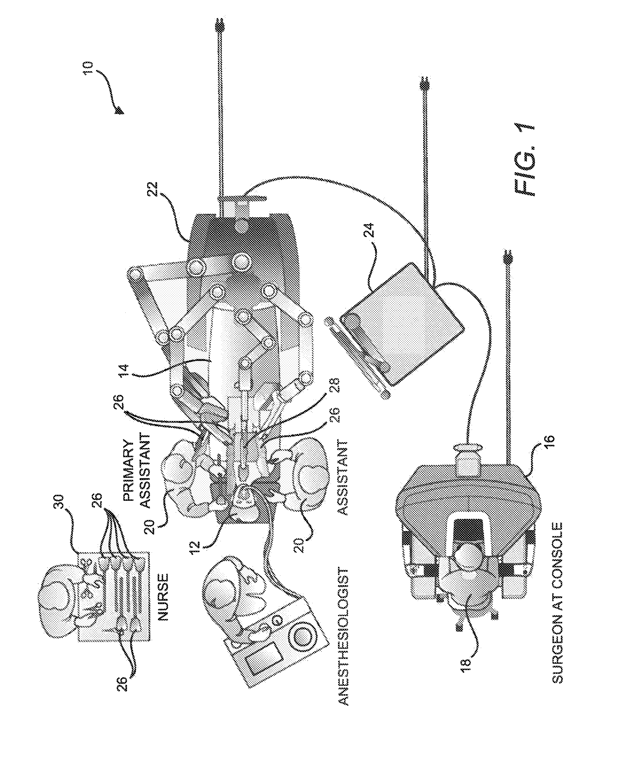
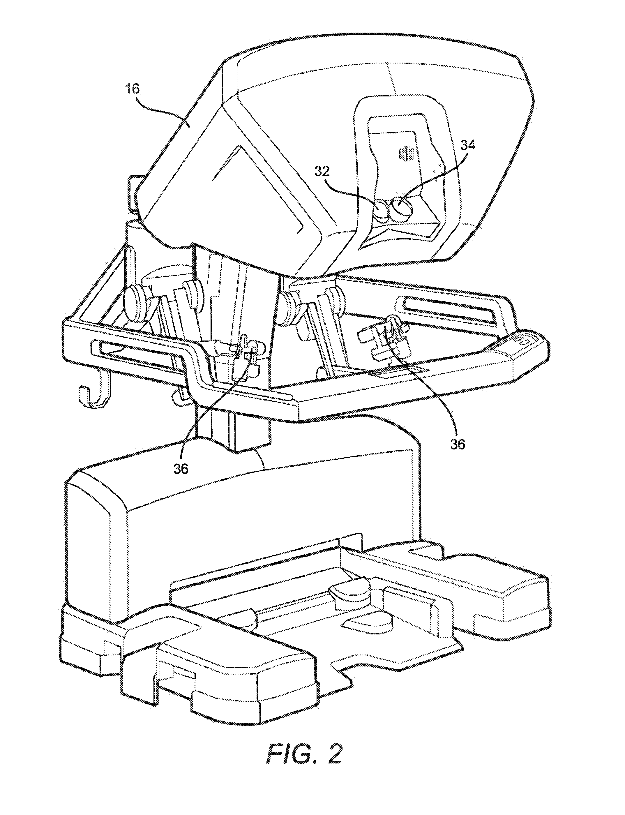
[0056]Referring now to the drawings, in which like reference numerals represent like parts throughout the several views, FIG. 1 is a plan view illustration of a Minimally Invasive Robotic Surgical (MIRS) system 10, typically used for performing a minimally invasive diagnostic or s...


PUM


Abstract

Mechanisms, assemblies, systems, tools, and methods incorporating the use of an offset drive shaft within an independently rotating member are provided. An example mechanism includes a base and a main shaft mounted to rotate relative to the base, a first drive shaft mounted inside the main shaft, and a first drive feature engaged with the first drive shaft. The main shaft includes a proximal end, a distal end, and a main shaft rotational axis defined therebetween. The first drive shaft is offset from the main shaft rotational axis. A first drive feature rotational axis is defined for the first drive feature and is fixed relative to the base as the main shaft rotates. The first drive feature rotates the first drive shaft.

Description

CROSS-REFERENCES TO RELATED APPLICATIONS[0001]This application claims the benefit under 35 U.S.C. §119(e) of U.S. Patent Application No. 61 / 260,919 (filed Nov. 13, 2009; entitled “Motor Interface For Parallel Drive Shafts Within An Independent Rotating Member”), which is incorporated herein by reference. This application is also related to U.S. patent application Ser. No. ______ (concurrently filed; entitled “Wrist Articulation By Linked Pull Rods”)[Attorney Docket No. ISRG 02320 / US], U.S. patent application Ser. No. ______ (concurrently filed; entitled “Double Universal Joint”)[Attorney Docket No. ISRG 02340 / US], U.S. patent application Ser. No. ______ (concurrently filed; entitled “Surgical Tool Containing Two Degree of Freedom Wrist”)[Attorney Docket No. ISRG 02350 / US], and U.S. patent application Ser. No. ______ (concurrently filed; entitled “End Effector With Redundant Closing Mechanisms”)[Attorney Docket No. ISRG 02330 / US], all of which are incorporated herein by reference.BAC...

Claims


Application Information

Patent Timeline
IPC IPC(8): A61B19/00B25F5/00
CPCA61B19/2203A61B2019/2242A61B2017/00477A61B34/30A61B34/71A61B2017/2902A61B2034/304H04W84/12A61B17/068A61B2034/302A61B2017/2927A61B17/07207A61B17/115A61B2017/07214A61B17/072
Inventor DACHS, II, GREGORY W.MURPHY, TODD E.BURBANK, WILLIAM A.MCDONALD, WILLIAM A.SCHENA, BRUCE MICHAEL
Owner INTUITIVE SURGICAL OPERATIONS INC
Learn More