
Developing roller for electrophotographic image forming apparatus, and manufacturing method of the same

a technology of electrophotographic image and development roller, which is applied in the direction of electrographic process apparatus, optics, instruments, etc., can solve the problems of image defects and difficulty in obtaining high-quality images with high optical density, and achieve high optical density, reduce ghosting, and maintain optical density

Active Publication Date: 2011-05-12
HEWLETT PACKARD DEV CO LP
View PDF2 Cites 19 Cited by
  • Summary
  • Abstract
  • Description
  • Claims
  • Application Information

AI Technical Summary

Benefits of technology

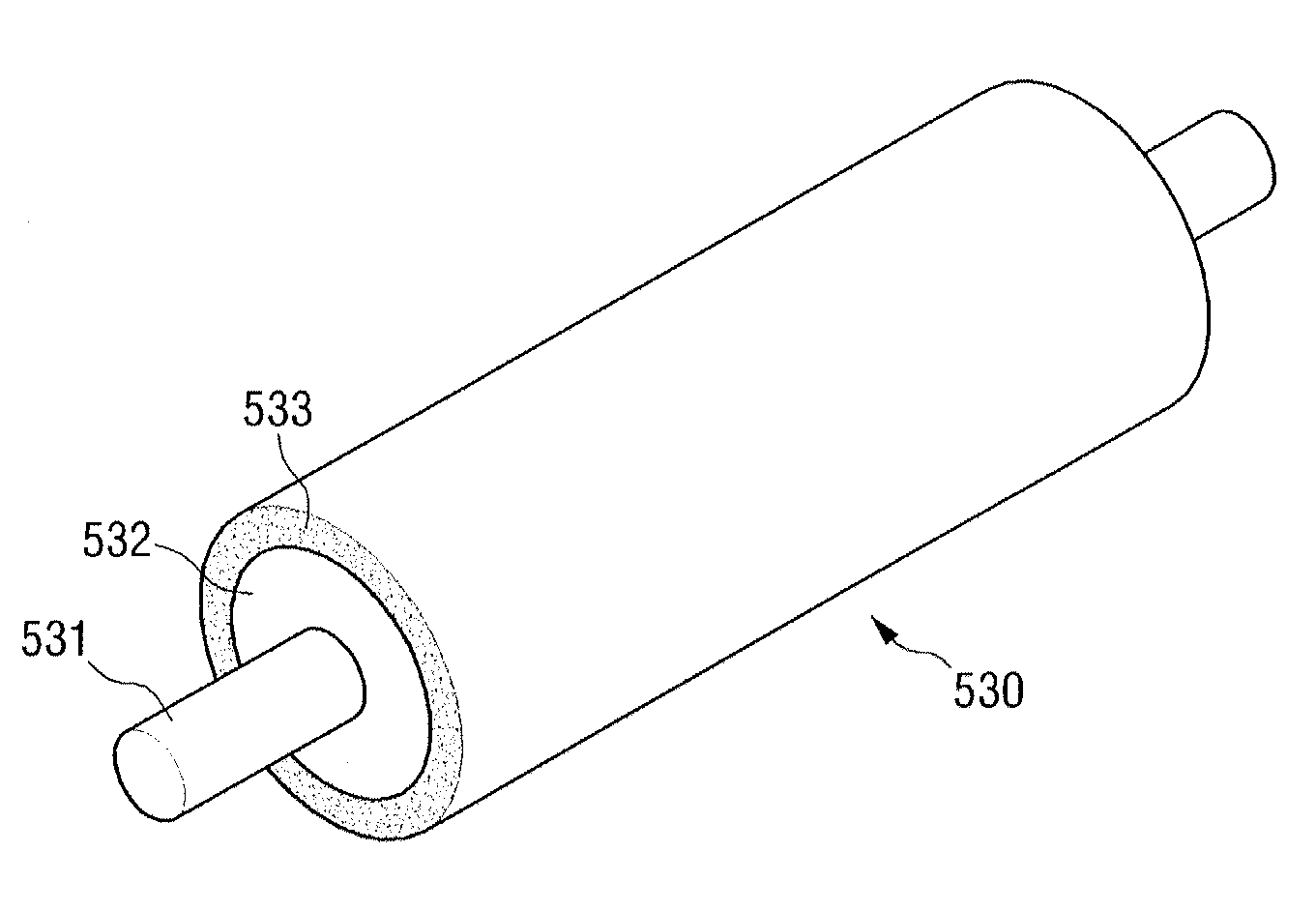
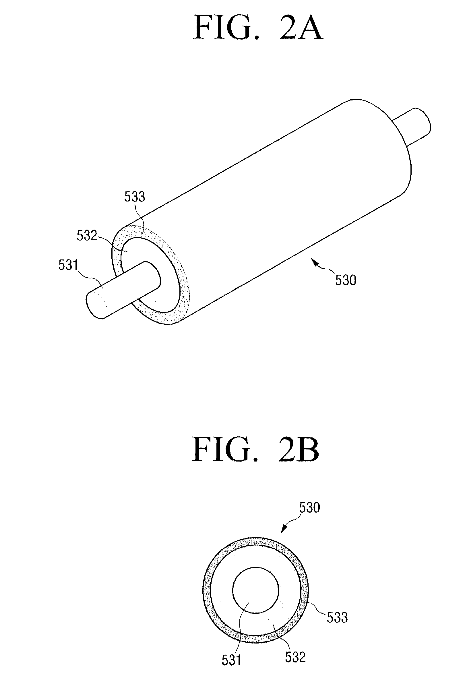
[0008]Aspects of the present disclosure provides a developing roller capable of maintaining a constant optical density, capable of reducing the occurrences of ghosts, and / or capable of achieving high optical density even in low temperature and in low humidity environments. Aspects of the present disclosure also provides a method of manufacturing the developing roller.

Problems solved by technology

Although a non-magnetic mono-component developer is widely used in the image developing art, due to the difficulty in controlling the charging of the toner, the toner being carried on the developing roller may be inconsistently or unstably charged, resulting in image defects such as, for example, ghosting.
It is particularly difficult to obtain high quality images with high optical density under lower temperature and / or in low humidity environments.

Method used


Image

  • Developing roller for electrophotographic image forming apparatus, and manufacturing method of the same
  • Developing roller for electrophotographic image forming apparatus, and manufacturing method of the same
  • Developing roller for electrophotographic image forming apparatus, and manufacturing method of the same

Examples


example 1

[0075]Spherical silica (Sunjin Chemical, 130NP) (100% by weight), silane compound N-(2-aminoethyl)-3-aminopropylmethyldimethoxysilane (ShinEtsu, KBM-602) (10% by weight), ethanol (250% by weight) were stirred with a stirrer for 48 hours, filtered, rinsed, and heated at 150° C. for 2 hours, thereby obtaining a surface-treated silica.

[0076]Polyester polyol (100% by weight), acrylic resin (5% by weight), conductive carbon black (8% by weight), the surface-treated silica prepared as described herein (70% by weight), the stabilizer represented by Formula 2 herein (2% by weight), and methylethylketone (500% by weight) were processed with a ball mill for 24 hours, and polyisocyanate (30% by weight) was then added to the mixture to yield a coating fluid for the conductive resin layer.

[0077]The coating fluid was dip coated on the conductive resilient layer of the semiconductive developing roller prepared as described herein, solidified by heating at 150° C., to form a conductive resin layer ...

example 2

[0078]Spherical silica (Sunjin Chemical, 130NP) (100% by weight), silane compound 3-aminopropyltriethoxysilane (ShinEtsu, KBM-903) (10% by weight), and ethanol (250% by weight) were stirred with a stirrer for 48 hours, filtered, rinsed, and heated at 150° C. for 2 hours to obtain a surface-treated silica. The developing roller was then prepared in the same manner as described herein in Example 1, except the developing roller used the surface-treated silica prepared as described herein.

example 3

[0079]The developing roller was prepared in the same manner as in Example 1, except 2% by weight of the stabilizer of Formula 5 herein was used.


PUM


Abstract

The disclosure provides a developing roller for an electrophotographic image forming apparatus, and a method of manufacturing the same. The developing roller includes a shaft member and a resilient member provided on the shaft member. The resilient member includes a conductive resilient layer in contact with the shaft member and a conductive resin layer defining the outer surface of the resilient member. The conductive resin layer includes a resin and a surface-treated metal oxide. The developing roller is capable of an increased amount of toner charging while stably maintaining optical density.

Description

CROSS-REFERENCE TO RELATED APPLICATIONS[0001]This application claims priority from Korean Patent Application No. 10-2009-0108639, which was filed in the Korean Intellectual Property Office on Nov. 11, 2009, the disclosure of which is hereby incorporated by reference in its entirety for all purposes.BACKGROUND[0002]1. Field of the Invention[0003]The disclosure relates generally to a developing roller for an electrophotographic image forming apparatus, and a manufacturing method of the same, and more specifically, to a developing roller that ensures an increased toner charging amount and a uniform optical density.[0004]2. Description of the Related Art[0005]An electrophotographic image forming apparatus, such as a laser printer, a facsimile, or a copier, generally employs an image forming configuration in which one or more of a charging roller, a developing roller and a transfer roller are arranged around a photosensitive medium. In an electrophotographic image forming apparatus of su...

Claims


Application Information

Patent Timeline
IPC IPC(8): G03G15/08
CPCG03G15/0818G03G2215/0634
Inventor LIM, AN-KEEKIM, TAE-HYUNYOU, MI-NA
Owner HEWLETT PACKARD DEV CO LP
Learn More