
Time-limiting mode (TLM) for an interleaved power factor correction (PFC) converter

a technology of power factor correction and time limitation, which is applied in the direction of electric variable regulation, process and machine control, instruments, etc., can solve the problems of increasing the size and cost of the devi

Inactive Publication Date: 2011-05-12
POLAR SEMICON
View PDF30 Cites 53 Cited by
  • Summary
  • Abstract
  • Description
  • Claims
  • Application Information

AI Technical Summary

Problems solved by technology

If the discharge cycle is not complete (i.e., current through the inductor at the beginning of the charging cycle is non-zero), the converter operates in a continuous conduction mode (CCM) that is detrimental to control of the output voltage.
However, this requires additional and larger hardware, thereby increasing the size and cost of the device.

Method used


Image

  • Time-limiting mode (TLM) for an interleaved power factor correction (PFC) converter
  • Time-limiting mode (TLM) for an interleaved power factor correction (PFC) converter
  • Time-limiting mode (TLM) for an interleaved power factor correction (PFC) converter

Examples


Embodiment Construction

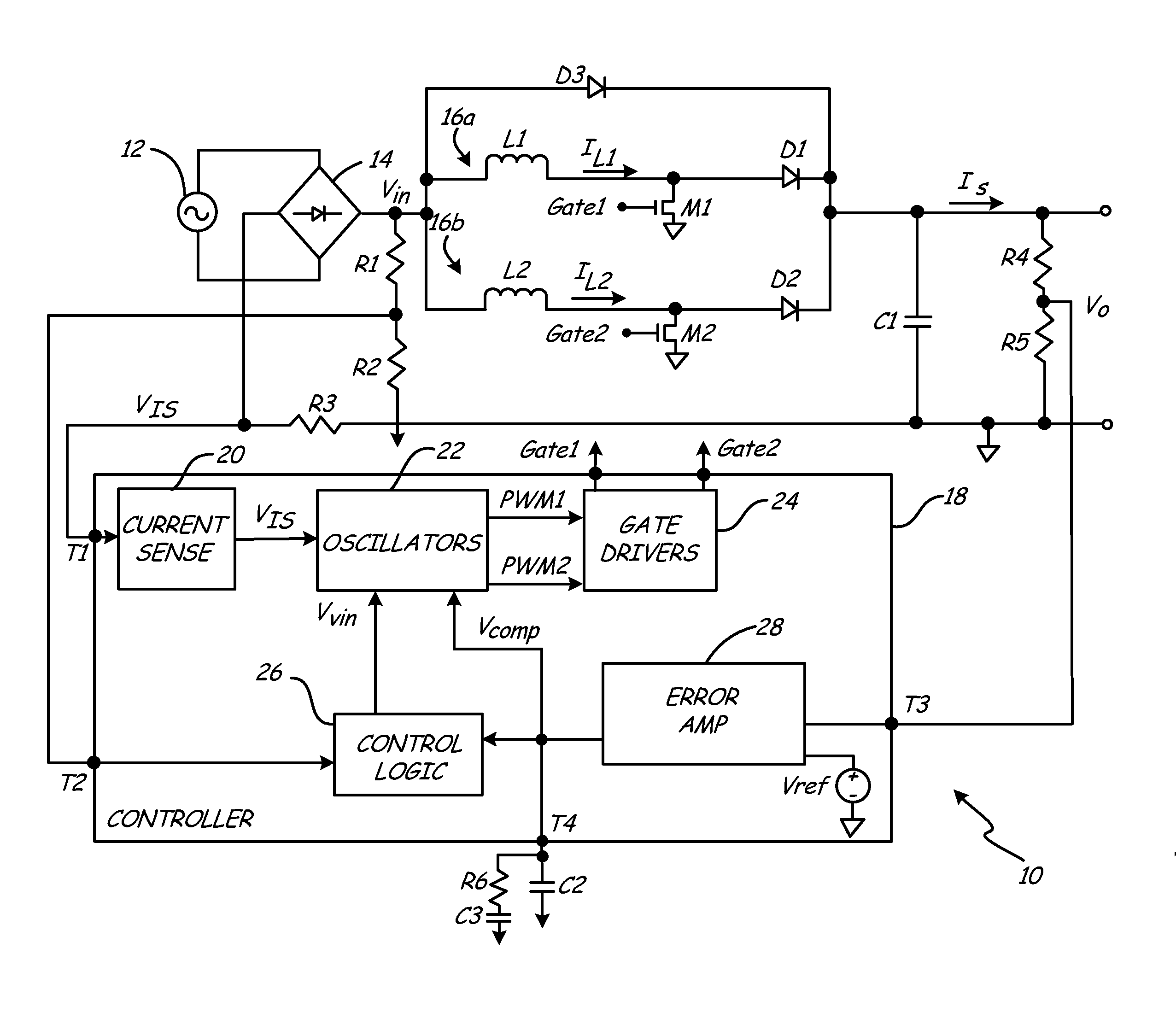
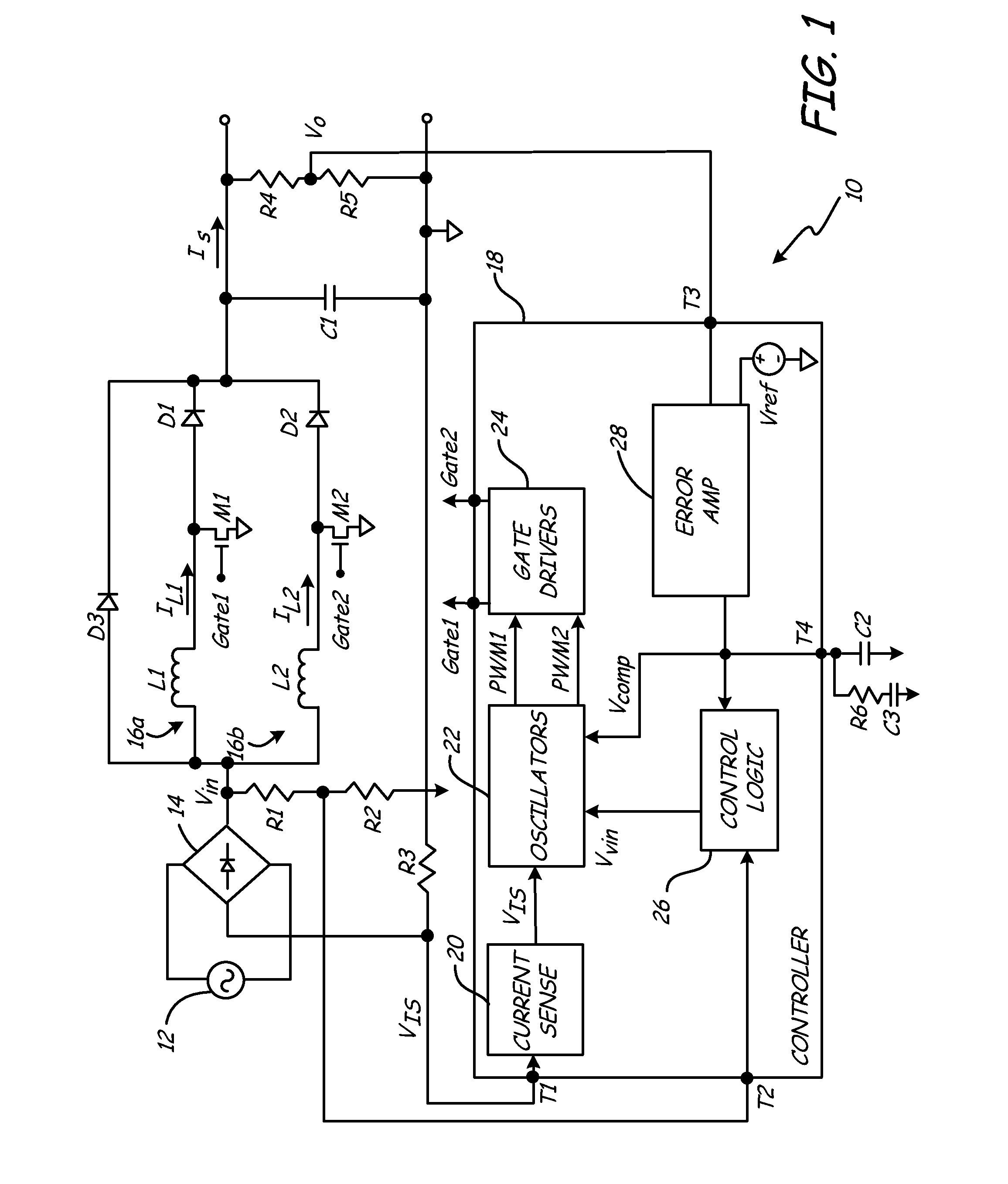
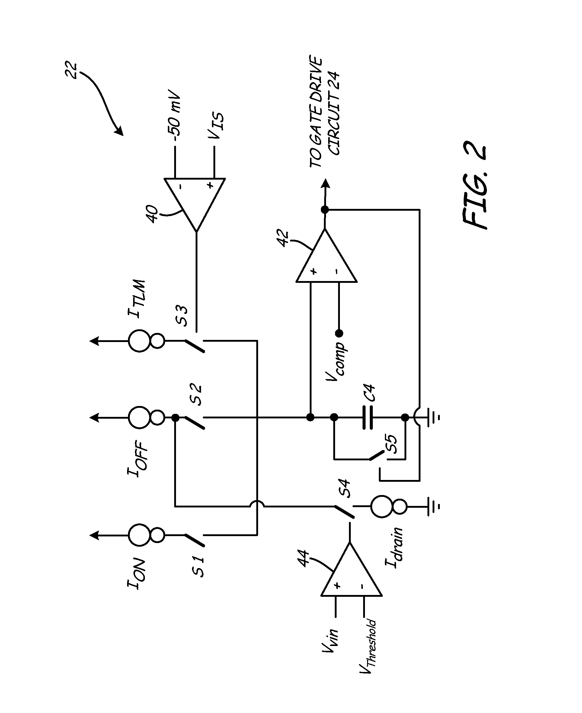
The present invention provides a system and method of controlling an interleaved power factor correction (PFC) circuit operating in a discontinuous conduction mode (DCM). The controller employs a normal mode of operation in which inductor currents in each PFC sub-circuit are estimated based on the monitored input voltage and monitored output voltage, and switching devices associated with each PFC sub-circuit are controlled to ensure DCM operation, in which OFF times ensure that inductor charging is initiated only after the inductor has been totally discharged (i.e., inductor current equals zero). As the input voltage increases, the OFF time associated with each PFC sub-circuit increases to ensure DCM operation. For interleaved PFC converters, the increased OFF time may result in a condition in which the inductor currents through each PFC sub-circuit do not overlap. In response, the controller activates a time-limiting mode (TLM) in which OFF time durations for each sub-circuit are b...


PUM


Abstract

The present invention provides a method of controlling an interleaved power factor correction (PFC) circuit operating in a discontinuous conduction mode (DCM). The controller employs a normal mode of operation in which inductor currents in each PFC sub-circuit are estimated based on the monitored input voltage and monitored output voltage, and switching devices associated with each PFC sub-circuit are controlled to ensure DCM operation. As the input voltage increases, the OFF times of each PFC sub-circuit increase such that the inductor currents no longer overlap. In response, the controller activates a time-limiting mode (TLM) in which OFF time durations for each sub-circuit are based on the monitored sum of load currents as opposed to the monitored input voltage and monitored output voltage.

Description

BACKGROUNDThe present invention relates to power factor correction (PFC) converters, and more particularly to interleaved PFC converters.Electric power is distributed almost universally in an alternating current (AC) format that allows for efficient transmission. Most devices however, including personal computers, televisions, etc., require direct current (DC) power. Power supplies act to convert the AC input supplied by a line to a DC output suitable for consumption by a device or load or act to convert a DC input to a DC output (i.e., a DC-to-DC converter). A switched-mode power supply (SMPS) employing a boost regulator is commonly employed in this role of AC-to-DC or DC-to-DC power conversion. A benefit of employing a SMPS having a boost regulator topology is the boost regulator can be controlled to provide power factor correction. Subsequent stages may be employed to step-down the output of the PFC boost regulator to a desired DC output voltage.A boost regulator includes an indu...

Claims


Application Information

Patent Timeline
IPC IPC(8): H02M7/23
CPCH02M1/4225Y02B70/126H02M2003/1586H02M3/1584Y02B70/10H02M3/1586
Inventor RAUSCH, GREGORY J.GABOURY, MICHAEL J.OSAKA, SHOHEI
Owner POLAR SEMICON
Learn More