
Wireless sensor

a sensor and wireless technology, applied in the field of sensors, can solve the problems of inflexibility, difficulty and expense associated with retrofitting for change, available sensors are not configured for wireless communication, and sensors are limited to certain types of signals

Active Publication Date: 2011-05-12
ABL IP HLDG
View PDF96 Cites 27 Cited by
  • Summary
  • Abstract
  • Description
  • Claims
  • Application Information

AI Technical Summary

Benefits of technology

The present invention is about a system and method for wirelessly detecting changes in an area. The system includes a sensor that detects changes in the area and a controller that controls the operation of light in the area. The sensor sends information about the change to the controller, which in turn controls the operation of the light. The system can detect changes in light levels or occupancy. The technical effect of the invention is to provide a convenient and efficient way to detect and respond to changes in an area, without the need for hard-wiring or complicated set-up procedures.

Problems solved by technology

Issues with such a scheme may include inflexibility and difficulty and expense associated with retrofitting for changing and / or growing installations.
Such presently available sensors are not configured for wireless communication.
As such, those sensors are limited to certain types of signals, such as those indicating detection of motion, or lack thereof.
Another challenge for such sensors in a conventional lighting control system is that such sensors are usually mounted at an elevated position (e.g., ceiling, wall).
As such, the sensor reading is inaccurate, thereby possibly resulting in inappropriate responses.
Other issues may include inflexibility to changing requirements of the occupants.
Sensors that are not sensitive enough may not detect fine movements (e.g., typing at a desk), and sensors that are over-sensitive may detect movement outside a door or window, resulting in responses that inappropriate to the actual situation in an area.

Method used


Image

  • Wireless sensor
  • Wireless sensor
  • Wireless sensor

Examples


Embodiment Construction

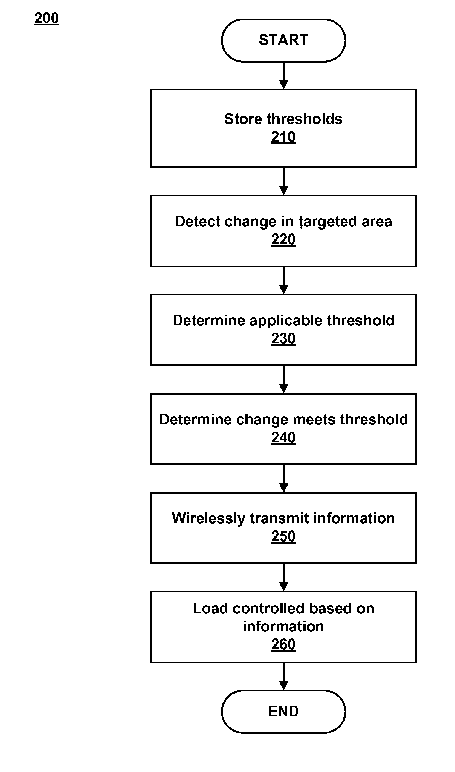
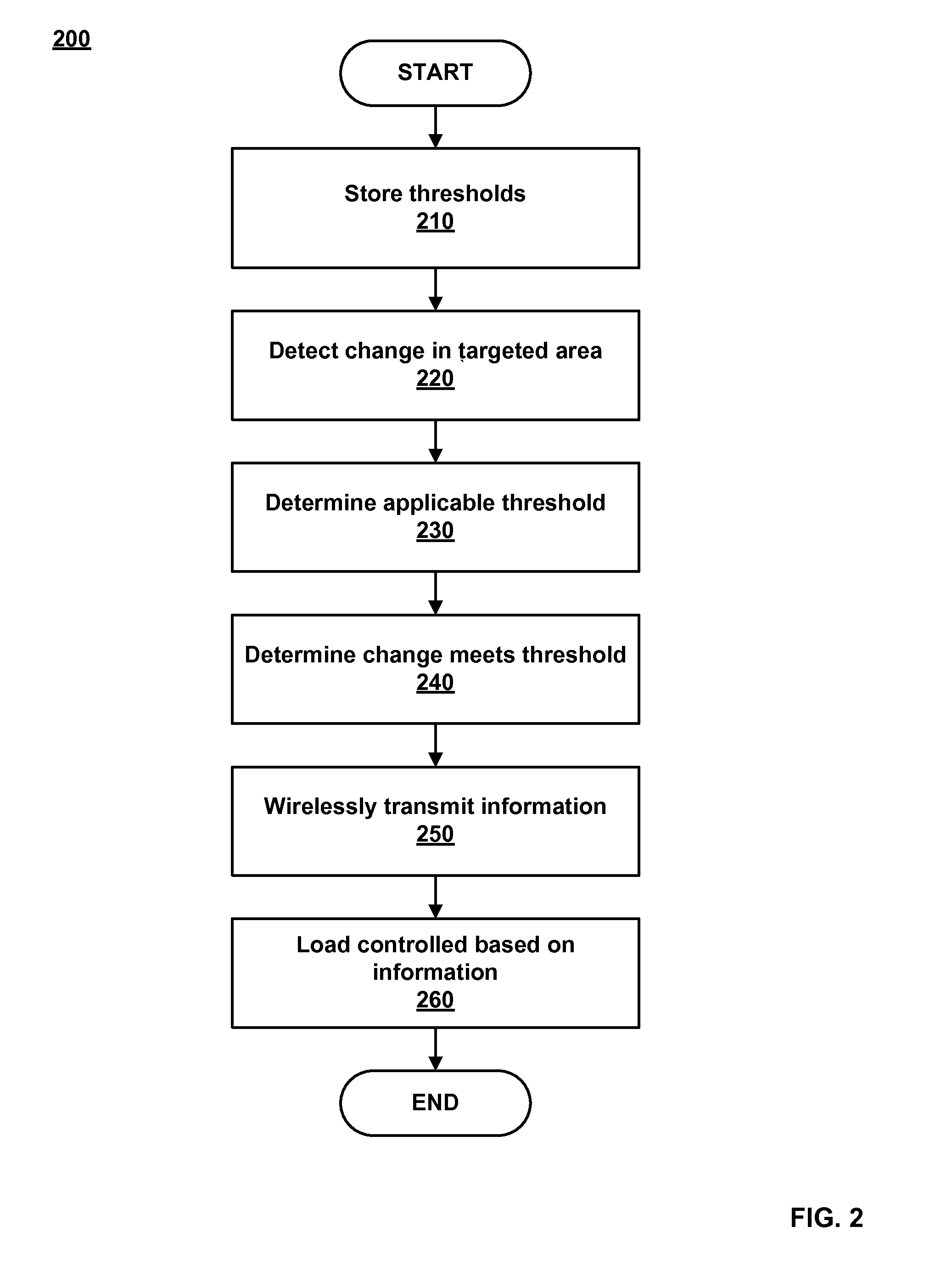
[0018]Embodiments of the present invention provide for wirelessly detecting area changes. Predetermined thresholds may be stored in memory. Each predetermined threshold is associated with a time of day, calendar day, and / or activity. The sensor may detect a change in the in the targeted area. The detected change is evaluated to determine an applicable threshold. Then it may be determined whether the detected change meets a predetermined threshold. If so, information regarding the change is wirelessly transmitted to an associated controller that controls light in the targeted area. The operation of the light may be controlled based on the wirelessly transmitted information.

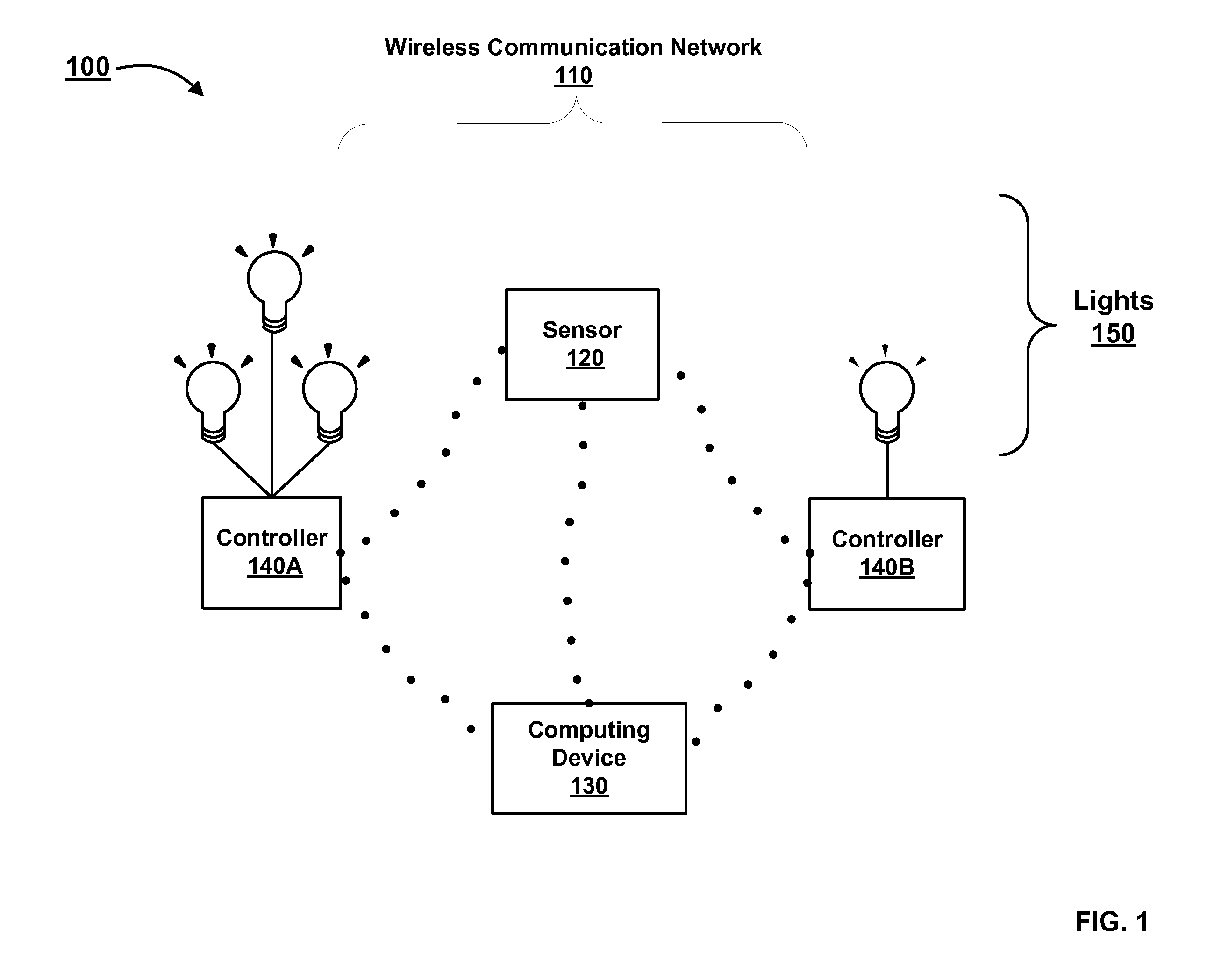
[0019]FIG. 1 illustrates an exemplary network environment 100 in which a system for wirelessly detecting area changes may be implemented. Communicating via a wireless communication network 110, devices in the network environment 100 include wireless sensor 120, computing device 130, and wireless controllers 140A-14...


PUM


Abstract

Systems and methods for wirelessly detecting area changes are provided. Predetermined thresholds may be stored in memory. Each predetermined threshold is associated with a time of day, calendar day, and / or activity. The sensor may detect a change in the in the targeted area. The detected change is evaluated to determine an applicable threshold. Then it may be determined whether the detected change meets a predetermined threshold. If so, information regarding the change is wirelessly transmitted to an associated controller that controls light in the targeted area. The operation of the light may be controlled based on the wirelessly transmitted information.

Description

CROSS-REFERENCE TO RELATED APPLICATIONS[0001]This application claims the priority benefit of U.S. provisional application No. 61 / 258,845 filed Nov. 6, 2009 and U.S. provisional application No. 61 / 258,841 filed Nov. 6, 2009, the disclosures of which are incorporated herein by reference.[0002]This application is also related to U.S. patent application Ser. No. 12 / 156,621 filed Jun. 2, 2008, U.S. patent application Ser. No. 12 / 380,727 filed Mar. 2, 2009, U.S. patent application Ser. No. 12 / 613,970 filed Nov. 6, 2008, and U.S. patent application Ser. No. 12 / 912,717 filed Oct. 26, 2010, the disclosures of which are also incorporated herein by reference.BACKGROUND OF THE INVENTION[0003]1. Field of the Invention[0004]The present invention generally involves sensors. More specifically, the present invention relates to wireless detection of area changes.[0005]2. Description of Related Art[0006]In recent years, a growing concern over environmental responsibility and viability has prompted var...

Claims


Application Information

Patent Timeline
Patent Type & Authority Applications(United States)
IPC IPC(8): G05B23/02
CPCG05B15/02G01N21/255G01V8/20G01N2021/1793G01N21/27H05B47/11H05B47/115Y02B20/40
Inventor HUIZENGA, CHARLESCORR, MICHAEL
Owner ABL IP HLDG
Learn More