
Press-contact pogo pin connector

a technology of pogo pins and pogo pins, which is applied in the direction of coupling device details, coupling contact members, coupling device connections, etc., can solve the problems of limited reduction in size, high manufacturing cost, and inability to reduce the overall height of the connector, so as to reduce the amount of metal materials used, reduce the size, and reduce the cost of materials

Active Publication Date: 2011-05-05
SMK CORP
View PDF5 Cites 11 Cited by
  • Summary
  • Abstract
  • Description
  • Claims
  • Application Information

AI Technical Summary

Benefits of technology

[0010]The present invention has been made in view of the foregoing problems in the conventional technology, and it is an object of the invention to provide a press-contact pogo pin connector having a machining cost lower than those of conventional connectors, can be easily reduced in height, and does not cause instantaneous interruption.
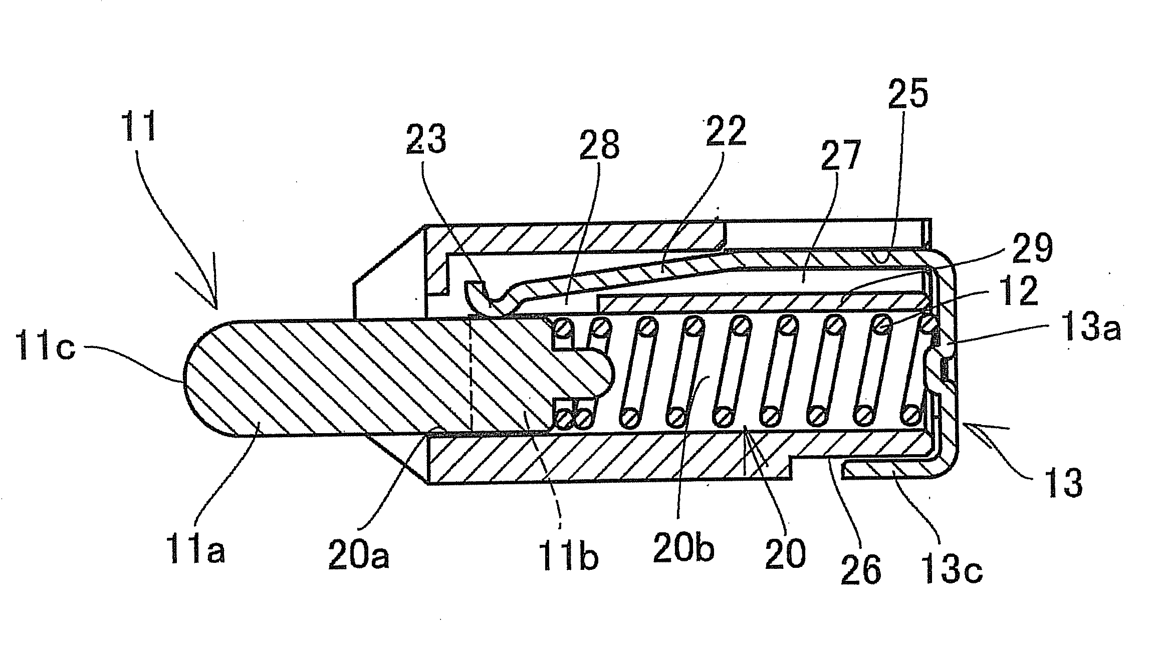
[0011]To solve the above problems and to achieve the above object, a first aspect of the present invention provides a press-contact pogo pin connector comprising: a molded insulating housing having a cylinder hole for allowing a pin to be installed therein, with a front opening of the cylinder hole provided on a front side of the housing; a pin that includes a flange portion at a rear end thereof and is installed inside the cylinder hole; a coil spring that is installed inside the cylinder hole and urges the pin so that the pin protrudes from the housing; and a contact that includes a substrate connection terminal portion and a contact spring portion and is secured to the housing, the substrate connection terminal portion and the contact spring portion being integrally provided, the contact spring portion extending inside the cylinder hole and being brought into press-contact with the pin at all times, wherein the flange portion of the pin urged by the coil spring abuts against a peripheral portion of the front opening of the cylinder hole so that the pin is prevented from falling off.

Problems solved by technology

Therefore, the manufacturing cost is high, and a reduction in size is limited due to mechanical machining.
Another problem is that, since the cylinder is installed inside a molded housing, the overall height of the connector cannot be small.
Still another problem is that, since the connector is configured such that the pin 3 can radially move within the cylinder 1, an instantaneous interruption can easily occur when an external shock is applied.
Therefore, the problem with this press-contact connector is that its height does not satisfactorily meet the low profile requirement when the connector is mounted in a direction parallel to a substrate.

Method used


Image

  • Press-contact pogo pin connector
  • Press-contact pogo pin connector
  • Press-contact pogo pin connector

Examples


Embodiment Construction

[0033]Next, preferred embodiments of the present invention will be described with reference to the drawings.

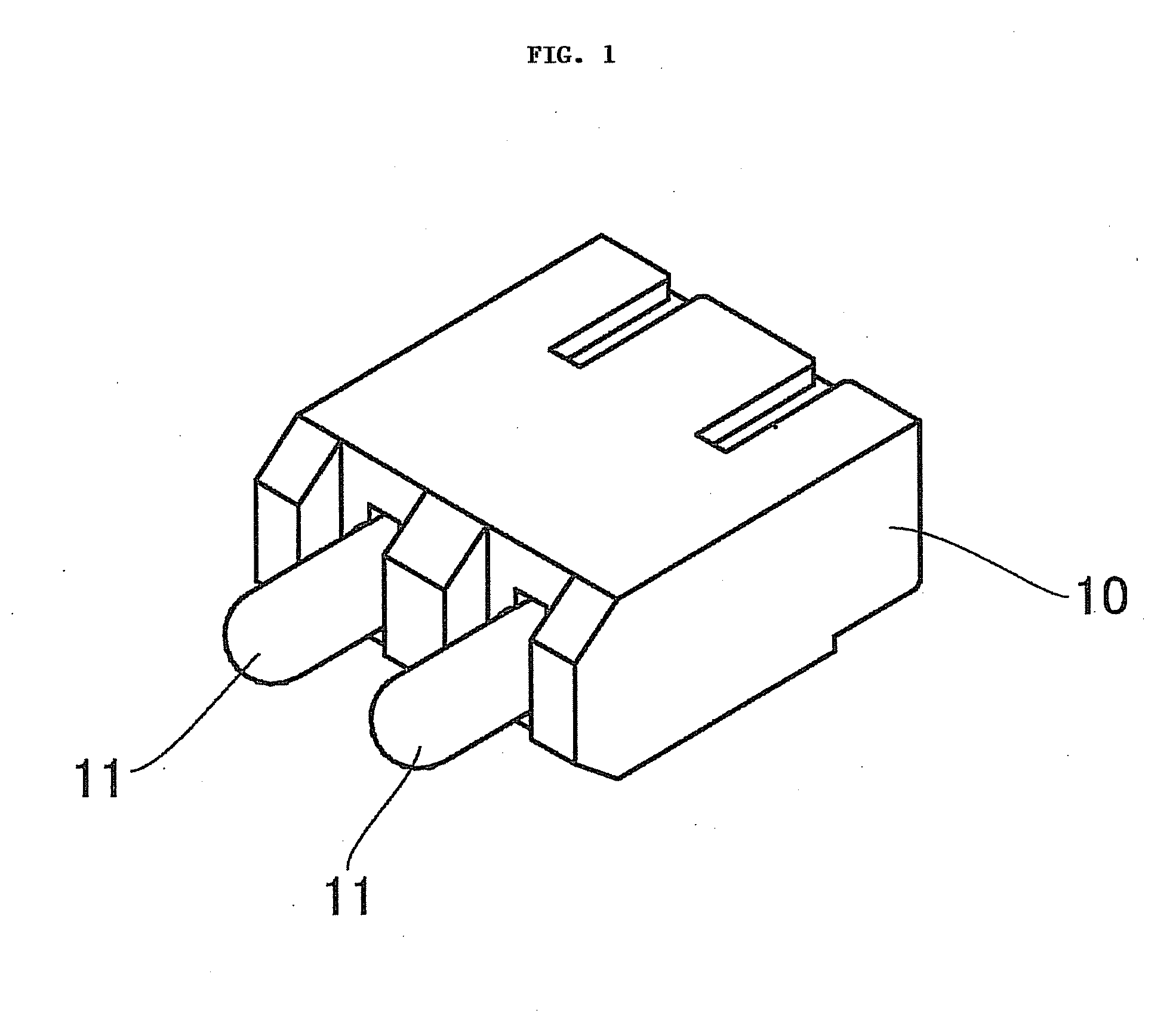
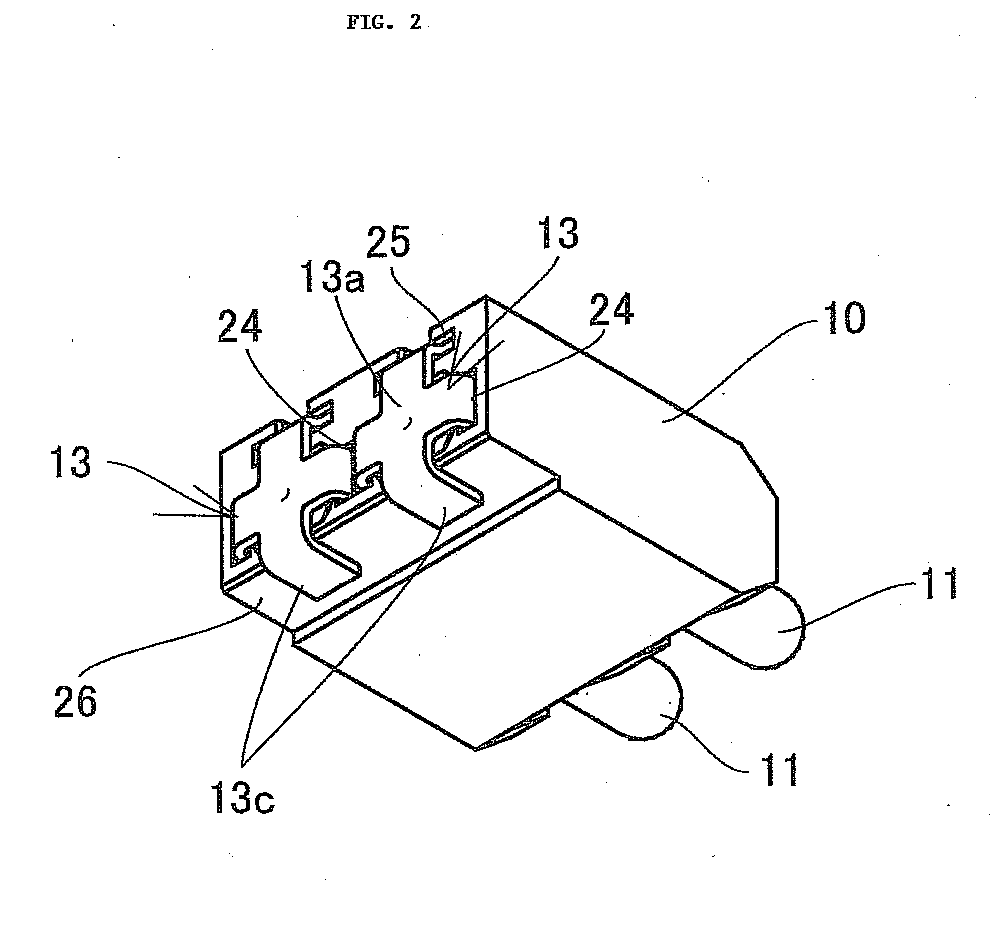
[0034]FIGS. 1 to 5C show a first exemplary embodiment of a press-contact pogo pin connector according to the present invention. In the first embodiment, a plurality of elastically protruding pogo pins (in the shown example, two (2) pins) are used in a battery connector. This press-contact pogo pin connector is composed of a housing 10, the pins 11, coil springs 12, and contacts 13. The pair of pins 11 are movably installed in the housing 10.

[0035]The housing 10 is molded of an insulating synthetic resin material and has a pair of cylinder holes 20 having openings on their front and rear ends. Each cylinder hole 20 has a circular front opening 20a that is provided on the front side of the housing. However, a main portion 20b of the cylinder hole 20 that is provided on the rear side of the housing and extends from the front opening 20a toward the contact 13 is formed to have a n...


PUM


Abstract

A press-contact pogo pin connector is provided which has a machining cost lower than those of conventional connectors, can be easily reduced in height, and does not cause instantaneous interruption. A molded insulating housing has a cylinder hole in which a pin is installed, and the pin installed inside the cylinder hole is urged by a coil spring installed inside the cylinder hole so as to protrude from the housing. A flange portion on the rear side of the pin urged by the coil spring abuts against the peripheral portion of the front opening of the cylinder hole on the front side of the housing so that the pin is prevented from falling off. A contact integrally includes a substrate connection terminal portion and a contact spring portion that extends inside the cylinder hole and is brought into press-contact with the pin at all times. The contact is secured to the housing.

Description

BACKGROUND OF THE INVENTION[0001]1. Field of the Invention[0002]The present invention relates to a press-contact pogo pin connector used mainly as a battery connector for small electronic devices such as mobile phones.[0003]2. Description of the Related Art[0004]Press-contact connectors with pogo pins are conventionally used as battery connectors for mobile phones.[0005]As show in FIG. 11, in conventional pogo pins used for such press-contact connectors, a pin 3 urged in its protruding direction by a coil spring 2 is movably installed inside a metal-made closed-end cylinder 1 with the end of a press-contact pin 3a of the pin 3 protruding from the end of the cylinder 1. The press-contact pin 3a is to be brought into press-contact with a contact terminal of a battery by the urging force of the coil spring 2 in the protruding direction.[0006]A bias cut surface 4 inclined with respect to the axial direction is formed on the cylinder-side inner end surface of the pin 3. The coil spring 2...

Claims


Application Information

Patent Timeline
IPC IPC(8): H01R4/52
CPCH01R13/2421
Inventor ASAI, KIYOSHIDOBASHI, MANABU
Owner SMK CORP
Learn More