
Image reading apparatus and image forming apparatus including the same

a reading apparatus and a technology of forming apparatus, applied in the field of reading apparatus, can solve the problems of uneven illumination, increased cost, uneven illumination, etc., and achieve the effects of suppressing uneven illumination, reducing bright spots, and increasing cos

Active Publication Date: 2011-05-05
SHARP KK
View PDF8 Cites 10 Cited by
  • Summary
  • Abstract
  • Description
  • Claims
  • Application Information

AI Technical Summary

Benefits of technology

[0015]It is an object of the present invention to provide an image reading apparatus, and an image forming apparatus provided with this image reading apparatus, in which light from a light source configured with a plurality of light-emitting elements disposed in a row in a main scanning direction is irradiated toward an original, and light reflected from the original is read with a photoelectric conversion element, in which without leading to high cost, it is possible to reduce bright spots on a light irradiation face of the original, and thus it is possible to suppress uneven illuminance due to the bright spots.
[0016]In light-emitting elements such as light-emitting diodes (LEDs) that have directional properties stronger in one direction, with respect to these directional properties, the size of the output light amount (that is, illuminance at the light irradiation face of an original) can affect the state of the bright spots on the light irradiation face of the original. For example, as the output light amount from the light-emitting elements decreases, bright spots are less likely to occur on the light irradiation face of the original, and so there is a tendency for uneven illuminance due to the bright spots on the light irradiation face of the original to be mitigated.

Problems solved by technology

Also, when a light source in which a plurality of light-emitting elements are disposed in a row in the main scanning direction is adopted as the light source provided in an image reading apparatus, because light-emitting elements such as LEDs have directional properties that are stronger in one direction, bright spots occur on the light irradiation face of the original, and these bright spots on the light irradiation face of the original may cause uneven illuminance.
However, limiting the light-emitting elements by specifying a luminance rank or increasing the number of mounted light-emitting elements so that uneven illuminance due to the bright spots does not occur results in increased cost.
However, with the image reading apparatus described in JP 2007-166065A, even assuming that it is possible to eliminate uneven concentration due to variation in the performance of individual light-emitting elements, it is not possible to reduce uneven illuminance due to bright spots on the light irradiation face of an original.

Method used


Image

  • Image reading apparatus and image forming apparatus including the same
  • Image reading apparatus and image forming apparatus including the same
  • Image reading apparatus and image forming apparatus including the same

Examples


Embodiment Construction

[0055]Hereinafter, an embodiment(s) of the present invention will be described with reference to the drawings. The embodiment(s) below are specific examples of the present invention, and are not of a nature limiting the technical scope of the present invention.

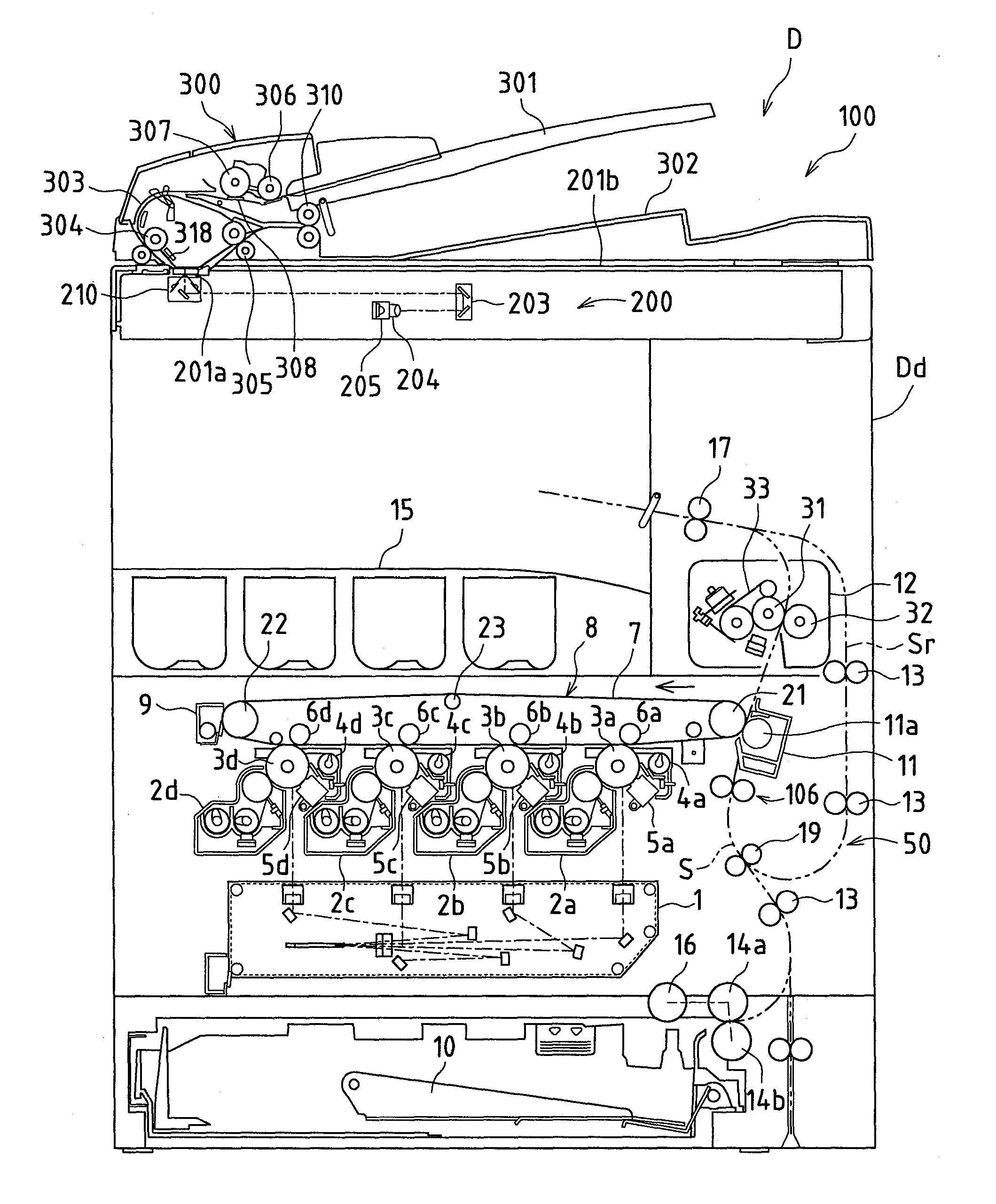
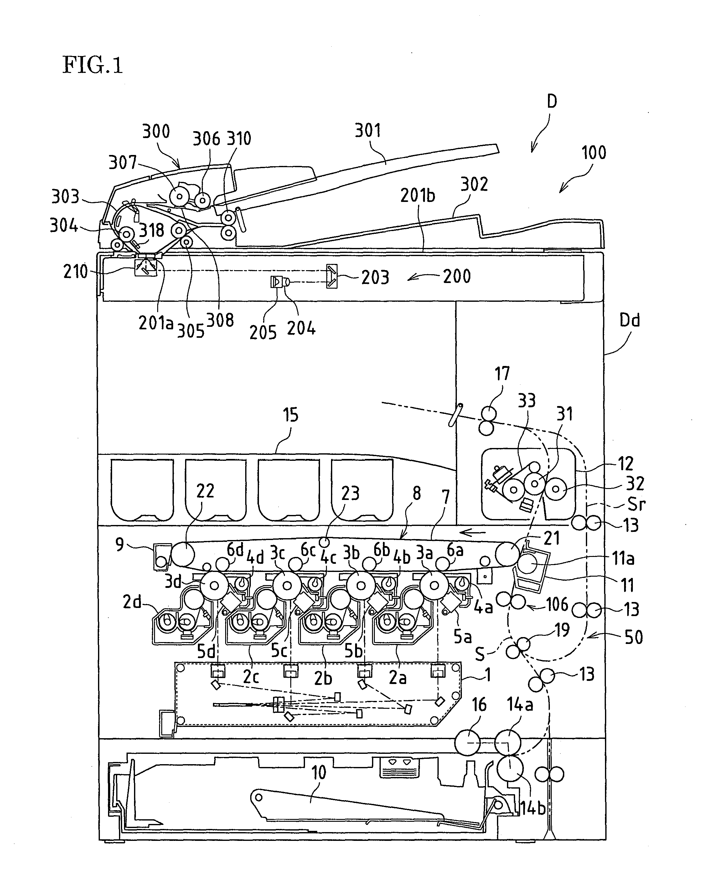
[0056]FIG. 1 is a cross-sectional view that schematically shows an image forming apparatus D provided with an image reading apparatus 100 according to an embodiment of the present invention.

[0057]The image forming apparatus D shown in FIG. 1 is provided with the image reading apparatus 100 that reads an image of an original G (see FIG. 2 and so forth described below), and an apparatus main body Dd that forms an image of the original G that has been read by the image reading apparatus 100 or an image that has been received from outside by recording the image in color or monochrome to ordinary paper or the like.

[0058][Overall Configuration of Image Forming Apparatus]

[0059]The apparatus main body Dd of the image forming apparatus...


PUM


Abstract

In one embodiment, an image reading apparatus has a light source configured with a plurality of light-emitting elements disposed in a row in a main scanning direction that irradiate light toward an original, and a photoelectric conversion element that receives light reflected from the original, an output light amount from the light-emitting elements can be adjusted, and a state of bright spots due to repetition of light-dark in the main scanning direction on a light irradiation face of the original due to the plurality of light-emitting elements is determined, and the output light amount from the light-emitting elements is adjusted based on the determination result of the state of the bright spots.

Description

CROSS-REFERENCE TO RELATED APPLICATIONS[0001]This application claims priority under 35 U.S.C. §119(a) on Patent Application No. 2009-253281 filed in Japan on Nov. 4, 2009, the entire contents of which are herein incorporated by reference.BACKGROUND OF THE INVENTION[0002]1. Field of the Invention[0003]The present invention relates to an image reading apparatus in which light from a light source configured with a plurality of light-emitting elements disposed in a row in a main scanning direction is irradiated toward an original, and light reflected from the original is read with a photoelectric conversion element, and also relates to an image forming apparatus provided with this image reading apparatus.[0004]2. Description of the Related Art[0005]In an image reading apparatus provided in an image forming apparatus such as a copy device, facsimile apparatus, or digital multifunction device, or an image reading apparatus capable of connection to a computer via a communications means suc...

Claims


Application Information

Patent Timeline
Patent Type & Authority Applications(United States)
IPC IPC(8): H04N1/04
CPCG03G15/04036H04N1/02815H04N1/02845H04N2201/0081H04N1/1013H04N1/40056H04N1/02865
Inventor NAKASHIMA, NORITOMO
Owner SHARP KK
Learn More