Method for Manufacturing Light-Emitting Element, Light-Emitting Element, Light-Emitting Device, Lighting Device, and Electronic Appliance

a technology of light-emitting elements and manufacturing methods, applied in semiconductor/solid-state device manufacturing, semiconductor devices, electrical devices, etc., can solve the problems of reduced light extraction efficiency, material lack of light reflectivity properties, and increase manufacturing costs, and achieve excellent reflecting properties, low cost, and favorable characteristics

Inactive Publication Date: 2011-05-05
SEMICON ENERGY LAB CO LTD
View PDF53 Cites 19 Cited by
  • Summary
  • Abstract
  • Description
  • Claims
  • Application Information

AI Technical Summary

Benefits of technology

[0027]According to one embodiment of the invention disclosed, an electrode is formed using a low cost material having an excellent reflecting property. As the layer which is in contact with the electrode, a layer which includes a composite material in which a metal oxide is contained in an organic compound is applied. This makes it possible to provide an inexpensive light-emitting element which has favorable characteristics.
[0028]That is, electrical characteristics (in particular, a hole-injection property) and a light reflectivity can be kept at high level, whereby sufficient light extraction efficiency can be achieved and power consumption is reduced. Further, since an inexpensive material is used, cost for manufacturing the light-emitting element can be reduced.
[0029]Furthermore, by using such a light-emitting element, power consumption of a light-emitting device (a lighting device) or a variety of electronic appliances is reduced and environmental load can be reduced.

Problems solved by technology

However, since these materials are relatively expensive, when the electrode is formed using these materials, there arises a problem that manufacturing cost increases.
Further, these materials lack sufficient properties in a light reflectivity.
Thus, when an electrode using any of these materials is formed, there arises a problem that light extraction efficiency decreases.

Method used


Image

  • Method for Manufacturing Light-Emitting Element, Light-Emitting Element, Light-Emitting Device, Lighting Device, and Electronic Appliance
  • Method for Manufacturing Light-Emitting Element, Light-Emitting Element, Light-Emitting Device, Lighting Device, and Electronic Appliance
  • Method for Manufacturing Light-Emitting Element, Light-Emitting Element, Light-Emitting Device, Lighting Device, and Electronic Appliance

Examples


embodiment 1

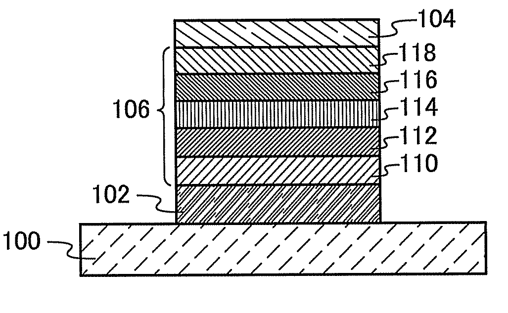
[0047]In this embodiment, a light-emitting element which is one embodiment of the disclosed invention is described with reference to FIG. 1.

[0048]The light-emitting element shown in FIG. 1 includes a first electrode 102, a second electrode 104, and an electroluminescence layer (hereinafter referred to as an EL layer 106) which is interposed between the first electrode 102 and the second electrode 104. Here, the first electrode 102 may be used as an anode while the second electrode 104 is used as a cathode, or the first electrode 102 may be used as a cathode while the second electrode 104 is used as an anode. In this embodiment, the case where the first electrode 102 functions as an anode and the second electrode 104 functions as a cathode is described as an example.

[0049]A substrate 100 functions as a supporting body of the light-emitting element. For the substrate 100, a glass substrate, a plastic substrate, a metal substrate, or the ...

embodiment 2

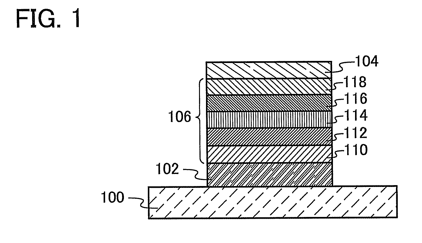
[0094]In Embodiment 2, an example of a light-emitting element in which a plurality of light-emitting units are stacked (hereinafter this light-emitting element is referred to as a stacked-type light-emitting element) will be described with reference to FIG. 2.

[0095]The light-emitting element shown in FIG. 2 has a first electrode 202, a second electrode 204, a first EL layer 206a and a second EL layer 206b which are interposed between the first electrode 202 and the second electrode 204, and a charge generation layer 208 which is interposed between the first EL layer 206a and the second EL layer 206b. Here, the structures of the first electrode 202 and the second electrode 204 are similar to those of the first electrode 102 and the second electrode 104 described in Embodiment 1. Further, the structures of the first EL layer 206a and the second EL layer 206b are similar to that of the EL layer 106 described in the above embodiment. Note that the fi...

embodiment 3

[0103]In this embodiment, an example of a light-emitting device that has a light-emitting element is described with reference to drawings.

[0104]First, an example of an active-matrix light-emitting device is described with reference to FIGS. 3A and 3B. FIG. 3A is a top view of the light-emitting device, and FIG. 3B is a cross-sectional view taken along lines A-A′ and B-B′ of FIG. 3A. The light-emitting device includes an element substrate 310 and a driver circuit portion (a source side driver circuit) 301, a pixel portion 302, a driver circuit portion (a gate side driver circuit) 303, and the like, over the element substrate 310. A filler is filled in a region 307 surrounded by the element substrate 310, a sealing substrate 304 and a sealing material 305. As a filler, an inert gas (such as nitrogen or argon) or a sealing material is used.

[0105]A lead wiring 308 is connected to the driver circuit portion 301 and the driver circuit portion 303. Note that the lead wiring 308 is a wiring...


PUM

PropertyMeasurementUnit
light reflectivityaaaaaaaaaa
reflectanceaaaaaaaaaa

Abstract

One object is to provide a light-emitting element which overcomes the problems of electrical characteristics and a light reflectivity have been solved. The light-emitting element is manufactured by forming a first electrode including aluminum and nickel over a substrate; by forming a layer including a composite material in which a metal oxide is contained in an organic compound so as to be in contact with the first electrode after heat treatment is performed with respect to the first electrode; by forming a light-emitting layer over the layer including a composite material; and by forming a second electrode which has a light-transmitting property over the light-emitting layer. Further, the first electrode is preferably formed to include the nickel equal to or greater than 0.1 atomic % and equal to or less than 4.0 atomic %.

Description

BACKGROUND OF THE INVENTION[0001]1. Field of the Invention[0002]One embodiment of the invention relates to a light-emitting element utilizing electroluminescence and a manufacturing method thereof. Further, one embodiment of the invention relates to a light-emitting device and a display device using the light-emitting element.[0003]2. Description of the Related Art[0004]In recent years, research and development have been extensively conducted on light-emitting elements using electroluminescence. In a basic structure of such a light-emitting element, a layer containing a substance having a light-emitting property is interposed between a pair of electrodes. By applying a voltage to this element, light emission can be obtained from the substance having a light-emitting property.[0005]Since the above light-emitting element is a self-luminous type, a display device using this light-emitting element has advantages such as high visibility, no necessity of a backlight, and the like. Further...

Claims


Application Information

Patent Timeline
Patent Type & Authority Applications(United States)
IPC IPC(8): H01L33/40H01L33/00
CPCH01L51/0021H01L51/0052H01L51/0059H01L33/40H01L51/5206H01L51/5265H01L51/5088H10K71/60H10K85/615H10K85/631H10K50/17H10K59/8051H10K59/80518H10K59/876H10K50/818H10K50/852
Inventor SUGISAWA, NOZOMUSASAKI, TOSHIKI
Owner SEMICON ENERGY LAB CO LTD
Why Eureka
Try Eureka