
Portable solids screening bucket

Inactive Publication Date: 2011-05-05
BEAM ROGER D +2
View PDF29 Cites 16 Cited by
  • Summary
  • Abstract
  • Description
  • Claims
  • Application Information

AI Technical Summary

Benefits of technology

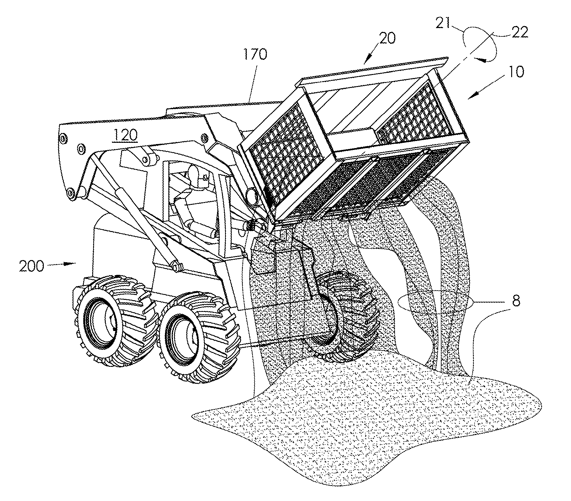
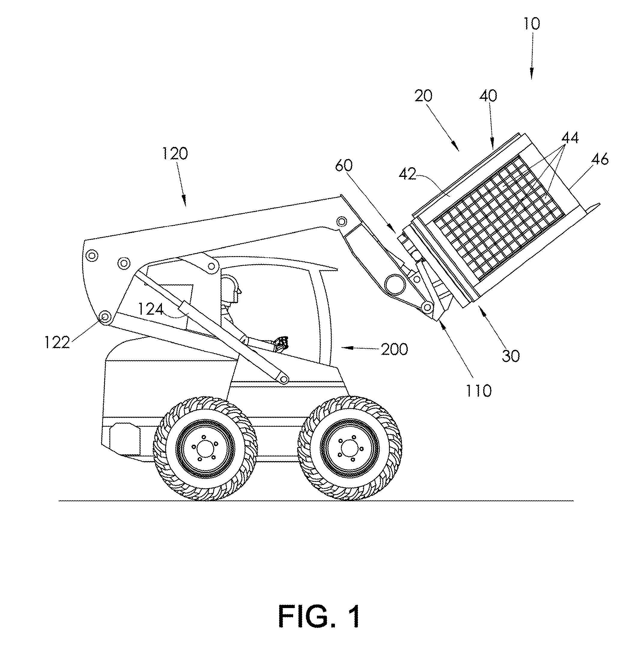
[0007]The problem of separating a portion of solid objects from a mixture of solid objects of varying sizes is addressed by providing a solids sifting apparatus comprising a bucket assembly comprised of a back wall, and a bucket framework joined to the back wall and extending forwardly therefrom, the bucket framework defining a lateral side wall comprised of a plurality of openings, and a forward perimeter defining a front opening; and means for rotating the bucket assembly relative to a mounting fixture around an axis perpendicular to the back wall of the bucket assembly. The apparatus is provided with the mounting fixture rotatably joined to the back wall of the bucket assembly for easy attachment to and operation by a utility vehicle, thereby making the apparatus highly portable between work sites.
[0011]The rotary drive power source may be a hydraulic motor. The rotatable driven member may be a ring gear, and the rotatable driving member may be a pinion gear engaged with the ring gear. Alternatively, the rotatable driven member may be a driven pulley, and the rotatable driving member may be a drive pulley engaged with the driven pulley by a drive belt. The back wall of the bucket assembly and the mounting fixture of the rotational assembly may be configured to form a shroud that encloses the rotatable driven member and the rotatable driving member, thereby protecting them from exposure to dirt and debris during operation of the sifting apparatus.

Problems solved by technology

However, these devices are generally relatively large in scale, are not easily and cost-effectively transported, and are provided as stand-alone single-use devices.

Method used


Image

  • Portable solids screening bucket
  • Portable solids screening bucket
  • Portable solids screening bucket

Examples


second embodiment

[0058]FIG. 11A-11C are perspective views of the solids sifting apparatus, the latter two of which are partially exploded. The solids sifting apparatus 300 is similar to the apparatus 10 of FIGS. 3-4B, and is comprised of a bucket assembly 320 including a back wall 330 and a bucket framework 340 joined to the back wall 330 and extending forwardly therefrom. The apparatus 300 is further comprised of a rotational assembly 360, and means for rotating the bucket assembly 320 relative to a mounting fixture 301 around an axis 321 perpendicular to the back wall 330 of the bucket assembly 320.

[0059]The bucket framework 340 defines a lateral side wall comprised of a plurality of openings, and a forward perimeter 346 defining a front opening. The lateral side wall of the bucket framework 340 may be comprised of a flat bottom wall 348, which may be a solids-impermeable wall without openings. Alternatively, the bottom wall 348 may include a plurality of openings 349, and / or the back wall 330 may...

third embodiment

[0064]FIG. 12A-12C are perspective views of the solids sifting apparatus, the latter two of which are partially exploded. The solids sifting apparatus 400 is similar to the apparatus 300 of FIGS. 11A-11C, and is comprised of a bucket assembly 420 including a back wall 430 and a bucket framework 440 joined to the back wall 430 and extending forwardly therefrom. The apparatus 400 is further comprised of a rotational assembly 460, and means for rotating the bucket assembly 420 relative to a mounting fixture 401 around an axis 421 perpendicular to the back wall 430 of the bucket assembly 420.

[0065]The main difference between the sifting apparatus 300 of FIGS. 11A-11C and the sifting apparatus 400 of FIGS. 12A-12C is that the rear wall 430 of the apparatus 400 is comprised of first and second engagement features, with the rotatable driven member (not shown, but substantially the same as member 370 of apparatus 300) being removably joined to the back wall 430 by engagement with the first ...


PUM


Abstract

A solids sifting apparatus comprising a bucket assembly comprised of a back wall and a bucket framework joined to the back wall and extending forwardly therefrom. The bucket framework defines a lateral side wall comprised of a plurality of openings, and a forward perimeter defining a front opening. The apparatus is further comprised of a rotational assembly comprising a mounting fixture comprising at least one attachment feature, a rotatable driven member joined to the back wall of the bucket assembly, a rotatable driving member coupled to the rotatable driven member; and a rotary drive power source operatively connected to the rotatable driving member and joined to the mounting fixture. The mounting fixture may include attachment features. A first attachment feature may comprise an upper lip extending rearwardly and downwardly from a mating plate, with second and third attachment features comprising first and second brackets extending outwardly from the mating plate.

Description

BACKGROUND OF THE INVENTION[0001]1. Field of the Invention[0002]Transportable solids separating apparatus that is attachable to a loader, bulldozer, tractor, skid steer, earth mover, or other vehicle, for separating solids of varying sizes from each other.[0003]2. Description of Related Art[0004]The capability to separate mixtures of earthen solids containing fines and larger solid objects is useful. One use is in the separation of soil from rocks, roots, and other large debris after performing a ground clearing operation. Another use is in the separation of sand and other small fines from coarser gravel. Another use is in ore mining, where it is desired to separate large chunks of ore from smaller fines at or near the point of extraction from the earth.[0005]The scale of these various operations may vary considerably. At the lower end of the scale, there is a need in the residential of commercial landscaping business to be able to separate mixtures of soil and rocks to produce fert...

Claims


Application Information

Patent Timeline
IPC IPC(8): B07B1/28
CPCB07B1/005B07B1/22E02F7/06E02F3/40E02F3/407E02F3/3681
Inventor BEAM, ROGER D.BEAM, RICHARD H.BEAM, MICHAEL M.
Owner BEAM ROGER D
Learn More