
Boundary layer effect turbine

Inactive Publication Date: 2011-04-28
SANDOVAL AARON +1
View PDF0 Cites 21 Cited by
  • Summary
  • Abstract
  • Description
  • Claims
  • Application Information

AI Technical Summary

Benefits of technology

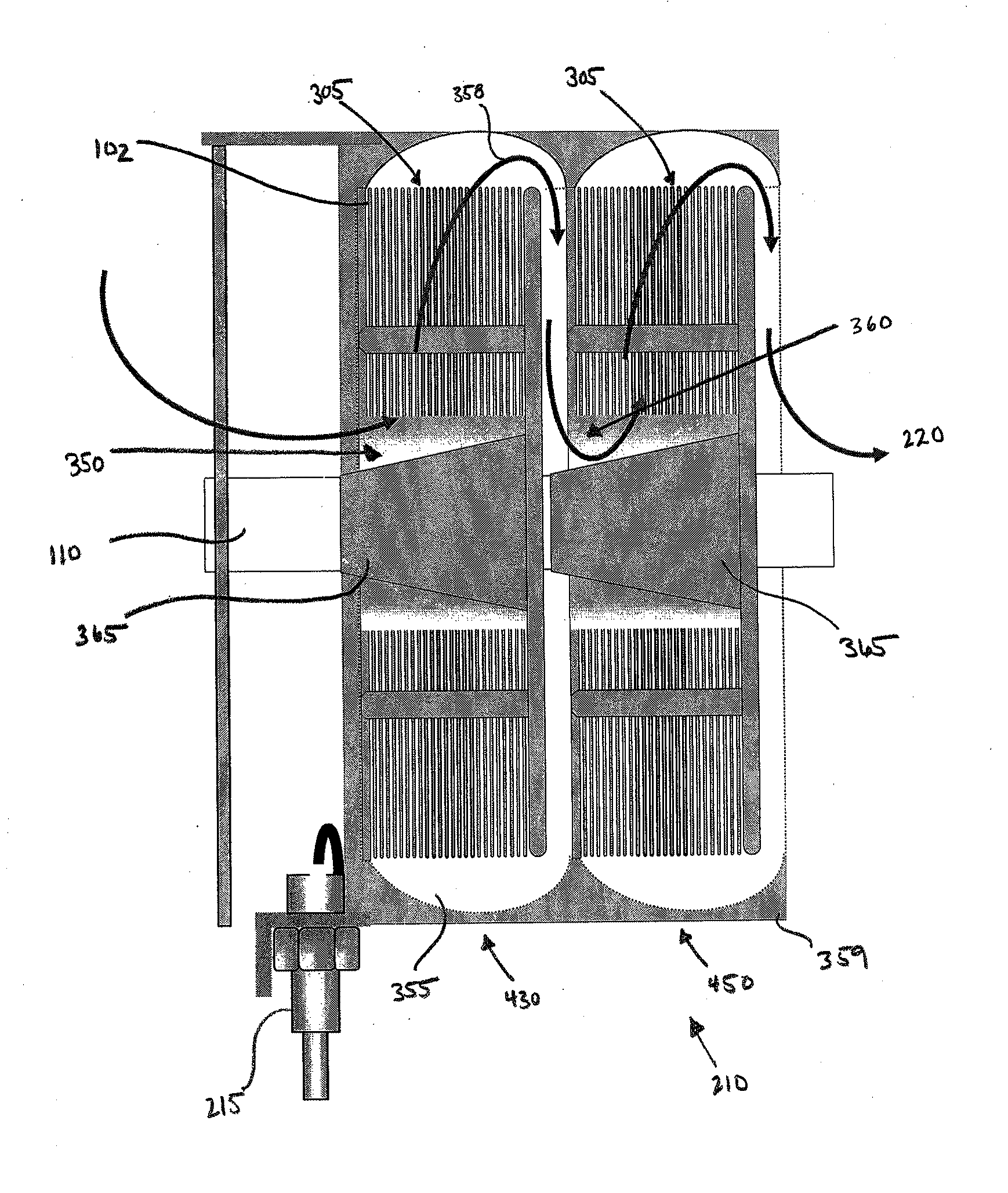
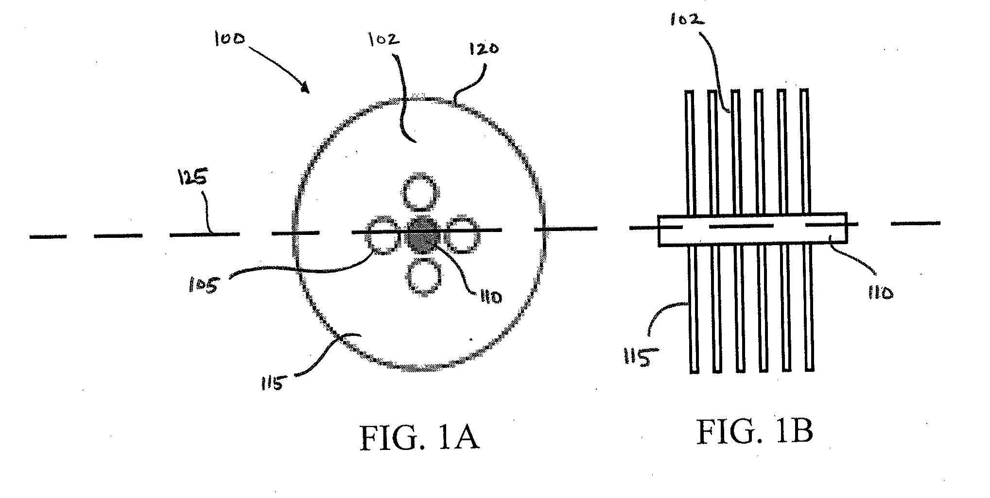
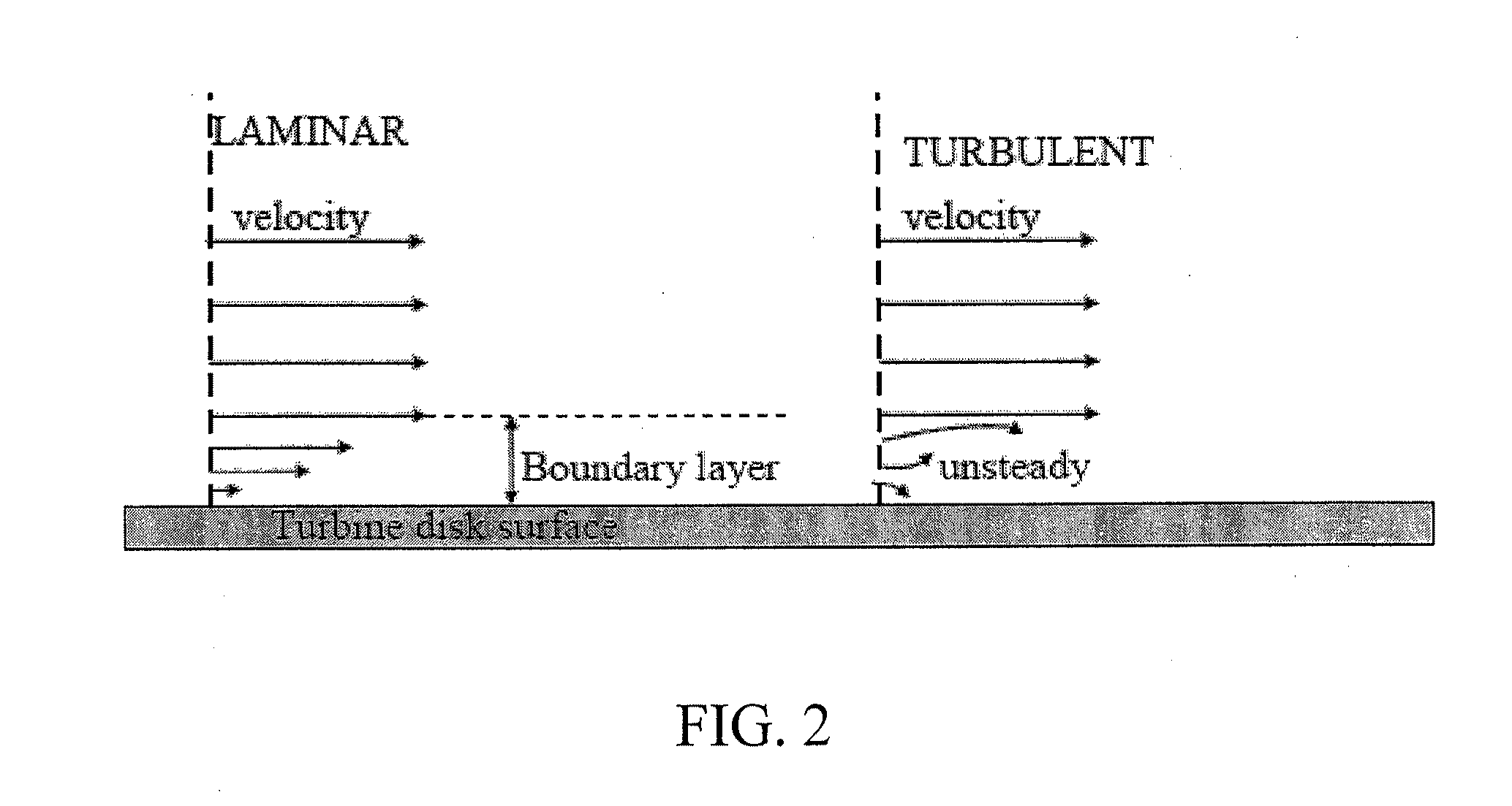
[0006]Described herein is a boundary layer effect turbine that utilizes the phenomena of the boundary layer to drive a turbine impeller that is made of a plurality of spaced disks oriented along a rotatable shaft. As operating fluid is directed over surfaces of the plurality of disks of the boundary layer effect turbine, energy is transferred from the fluid to the disks as a result of the adhesive and viscous properties of the fluid. The boundary layer effect turbine directs the operating fluid in a radially-converging spiral, or vortical, path through narrow spaces between the plurality of disks and drives the shaft for the generation of electric power or for mechanical work. As explained further below, the boundary layer effect turbine of this disclosure provides embodiments that enhance the operation of the microturbine beyond the capabilities of the internal combustion engine or blade turbine.
[0022]Some embodiments provide that the arcuate elevation comprises substantially an airfoil shape. In some embodiments, the arcuate elevation has a thickness equal to the space between adjacent disks, and in some embodiments, the arcuate elevation has a thickness greater than the boundary layer space between adjacent disks. Some embodiments provide that during rotation of the central shaft, the plurality of arcuate elevations directs fluid flowing across the face of the disk in a radially outward direction, and in some embodiments, during rotation of the central shaft, the plurality of arcuate elevations directs fluid flowing across the face of the disk in a radially inward direction. In some embodiments, the arcuate elevations present a surface, which induces a near positive displacement of the fluid moving between the disks, enhancing the mechanical efficiency of the boundary layer effect. In some embodiments, at least one of the arcuate elevations comprises a thickness equal to about twice the thickness of a laminar flow boundary layer of a fluid that flows into the housing from the fluid inlet port and across the face of at least one of the disks. In some embodiments, at least two of the disks are spaced about 0.6 mm apart, and in some embodiments, at least two of the disks are spaced about 1.2 mm apart.
[0037]Some embodiments described herein provide a high speed permanent magnet starter generator which is mounted on the same shaft as other rotating assemblies. Some embodiments provide for the starter generator to be water cooled by water having a temperature lower than the ambient temperature in order to reduce the compressor inlet air temperature and enhancing compressor efficiency. In some embodiments, the casing of the starter generator may be provided with extended surfaces or fins to facilitate heat exchanging.

Problems solved by technology

These shortcomings include their complex construction and inherent inefficient operations.

Method used


Image

  • Boundary layer effect turbine
  • Boundary layer effect turbine
  • Boundary layer effect turbine

Examples


Embodiment Construction

[0096]The boundary layer effect turbine described herein has several advantages over the internal combustion engine and the blade turbine. The internal combustion engine is a complex system that has several moving parts that are arranged about a rotating crankshaft. While the internal combustion engine has been used for many purposes in many industries, the complex construction presents significant maintenance complications. Additionally, the reciprocating motion between various components of the internal combustion engine (e.g., the piston within the cylinder) results in the generation of heat caused by the friction between parts. The heat results in losses that decrease the efficiency of the internal combustion engine.

[0097]Similarly, the blade turbine is also plagued with complications arising from its principle of operation. Cavitation occurs as the operating fluid engages the blades moving at extremely high speeds. This damages the blades and presents different, but significant...


PUM


Abstract

Described herein are embodiments of a boundary layer effect turbine and a hydrodynamic speed reducer. Described is a boundary layer effect turbine that utilizes the phenomena of the boundary layer to drive a turbine impeller that is made of a plurality of spaced disks oriented along a rotatable shaft. As operating fluid is directed over surfaces of the plurality of disks of the boundary layer effect turbine, energy is transferred from the fluid to the disks as a result of the adhesive and viscous properties of the fluid.

Description

RELATED APPLICATIONS[0001]The present application is a §371 national phase application filing of Application No. PCT / US2008 / 088687, with an international filing date of Dec. 31, 2008, and which claims priority benefit from U.S. Provisional Application No. 61 / 018,089, filed Dec. 31, 2007, the entire contents of both of which are hereby incorporated herein by reference.FIELD OF THE DISCLOSURE[0002]The present disclosure relates to a boundary layer effect gas microturbine for the purpose of producing a torque for mechanical work or to generate electric power.BACKGROUND OF THE DISCLOSURE[0003]Reciprocating internal combustion engines have long been used to replace man power with that of the machine. In these engines, a linear motion is imparted to one or more reciprocating pistons by compression and ignition of a mixture of fuel and air. The linear motion of the one or more pistons is converted to rotational motion by connection of a connecting rod to a crankshaft. The rotation motion i...

Claims


Application Information

Patent Timeline
IPC IPC(8): F04D13/04
CPCF01D1/36F01D9/026F01D15/005F05D2250/82F02C3/09F02C7/08F02C3/05
Inventor SANDOVAL, AARONWINGARD, JOHANN
Owner SANDOVAL AARON
Learn More