
Liquid crystal display panel driving circuit

a technology of driving circuit and display panel, which is applied in the direction of electric digital data processing, instruments, computing, etc., can solve the problems of increasing manufacturing costs and achieve the effect of reducing circuit area

Active Publication Date: 2011-04-28
SILICON WORKS CO LTD
View PDF4 Cites 38 Cited by
  • Summary
  • Abstract
  • Description
  • Claims
  • Application Information

AI Technical Summary

Benefits of technology

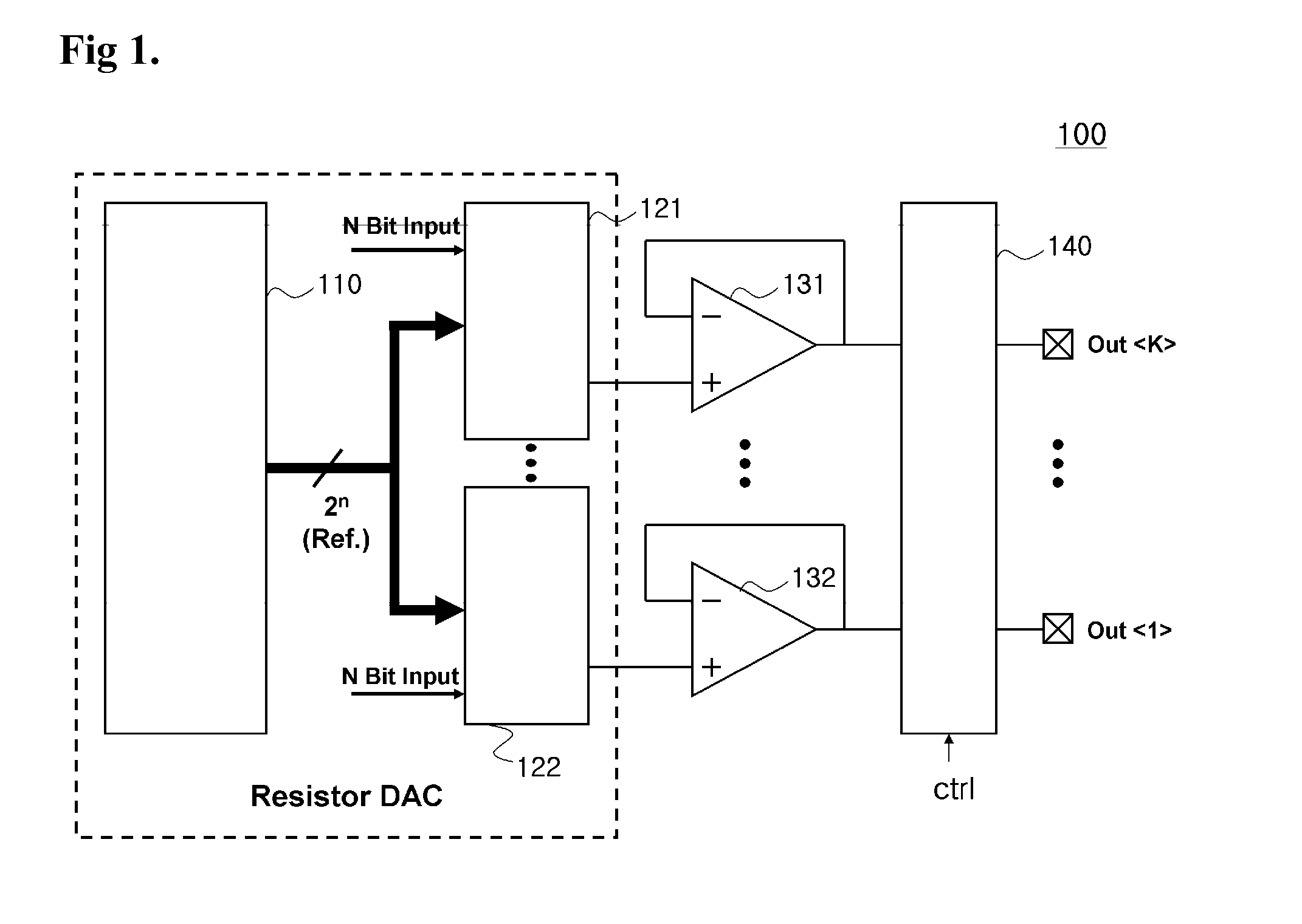
[0014]Accordingly, the present invention has been made in an effort to solve the problems occurring in the related art, and an object of the present invention is to provide a liquid crystal display panel driving circuit with a significantly reduced circuit area, in which the area of a DAC circuit taking the bulk of the liquid crystal display panel driving circuit can be significantly reduced by allowing functions of the DAC circuit to be partially performed by an amplifier.

Problems solved by technology

As a result, the manufacturing cost may increase.

Method used


Image

  • Liquid crystal display panel driving circuit
  • Liquid crystal display panel driving circuit
  • Liquid crystal display panel driving circuit

Examples


Embodiment Construction

[0023]Reference will now be made in greater detail to a preferred embodiment of the present invention, an example of which is illustrated in the accompanying drawings.

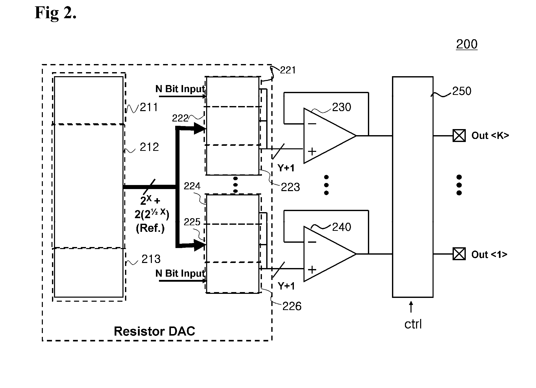
[0024]FIG. 2 is a diagram illustrating a liquid crystal display driving circuit in accordance with an embodiment of the present invention.

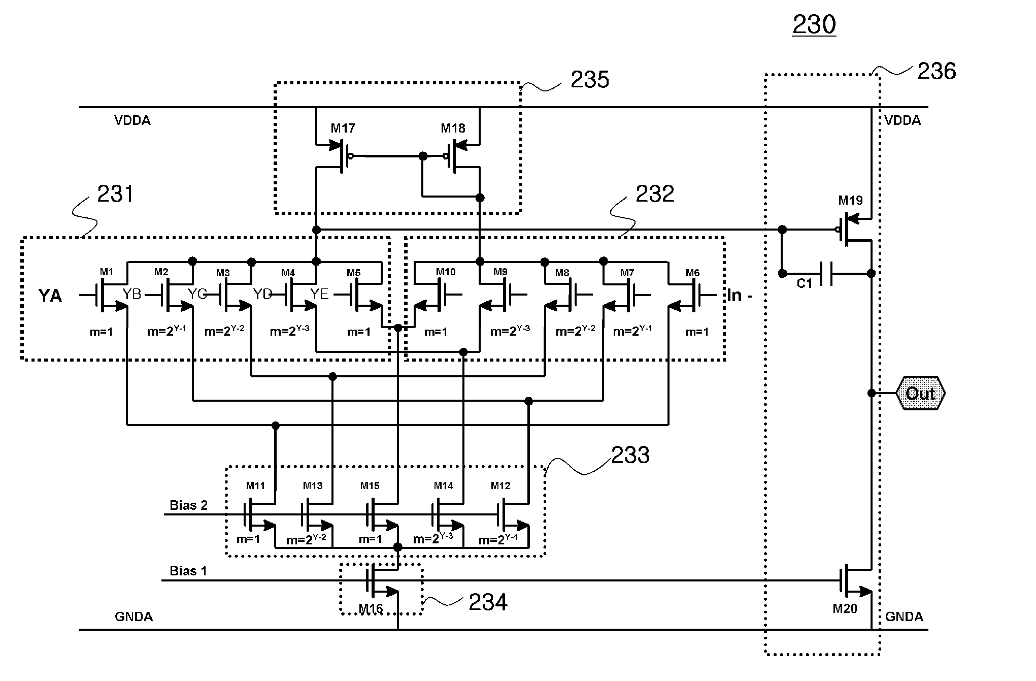
[0025]The liquid crystal display driving circuit 200 illustrated in FIG. 2 includes resistor string units 211 to 213 according to areas, DAC switching units 221 to 226 according to areas, interpolation amplifiers 230 and 240, and an output switch unit 250.

[0026]Referring to FIG. 3, inputted N-bit digital data (N bit input) includes upper X bits and lower Y bits (X and Y is an integer which is equal to or more than 0). For example, when the N-bit digital data (N bit input) is 10 bits and the upper X bits are 7 bits, the lower Y bits are 3 bits.

[0027]The resistor string units 211 to 213 according to areas are configured to output analog reference voltages at different ratios according ...


PUM


Abstract

Disclosed is a liquid crystal display panel driving circuit for driving a liquid crystal display panel with a resolution of N bits. N-bit digital data including upper X bits and lower Y bits is inputted. The liquid crystal display panel driving circuit includes a resistor string unit according to areas, a DAC converter switching unit according to areas, and an interpolation amplifier. The resistor string unit outputs analog reference voltages at different ratios according to three areas. The DAC converter switching unit receives the N-bit digital data, selects (Y+1) analog voltages from the analog reference voltages based on the upper X bits, outputs the (Y+1) analog voltages, and outputs the (Y+1) analog voltages of different combinations based on the lower Y bits. The interpolation amplifier receives the (Y+1) analog voltages and generates an interpolated output voltage by setting weights for the (Y+1) analog voltages by using multi-factors.

Description

BACKGROUND OF THE INVENTION[0001]1. Field of the Invention[0002]The present invention relates to a liquid crystal display panel driving circuit, and more particularly, to a liquid crystal display panel driving circuit with a significantly reduced area.[0003]2. Description of the Related Art[0004]Recently, the resolution of a display panel such as a television has been increased day by day. With the increase in the resolution of the display panel, the size of a driving circuit for driving a panel in a source driver IC (integrated circuit) of a display apparatus has also been increased.[0005]In such a liquid crystal display panel driving circuit, the area of a circuit is an important factor. When the size of the driving circuit is increased, since the manufacturing cost of the liquid crystal display driving circuit and system is increased and thus competitiveness thereof is reduced, technologies for reducing the area of the liquid crystal display driving circuit are required.[0006]FIG...

Claims


Application Information

Patent Timeline
Patent Type & Authority Applications(United States)
IPC IPC(8): G09G3/36G09G5/00
CPCG09G3/20G09G2310/027G09G3/3696G09G3/3685G09G3/36
Inventor CHO, HYUN-HOKIM, JI-HUNNA, JOON-HOOH, HYUNG-SEOGKIM, DAE-SEONGHAN, DAE-KEUN
Owner SILICON WORKS CO LTD
Learn More