
Magnetic force based automatic power generation device

a technology of automatic power generation and magnetic force, applied in the direction of dynamo-electric convertors, electrical apparatus, dynamo-electric machines, etc., can solve the problems of no practical perpetual machine developed and created, continuous energy crises, and no practical power generation device developed and tested. , to achieve the effect of low energy consumption and high efficiency power generation

Inactive Publication Date: 2011-04-28
LEE CHIU FA
View PDF18 Cites 6 Cited by
  • Summary
  • Abstract
  • Description
  • Claims
  • Application Information

AI Technical Summary

Benefits of technology

[0003]The primary objective of the present invention is to provide a magnetic force based automatic power generation device, which realizes high efficiency power generation through starting and maintaining the operation of a power generation device in a low energy consumption manner, and thus realizing environmental protection and energy conservation.
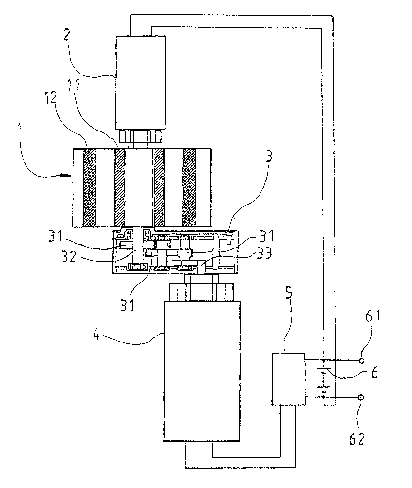
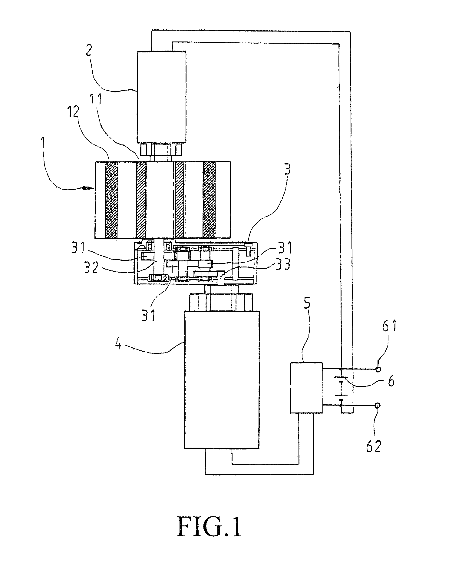
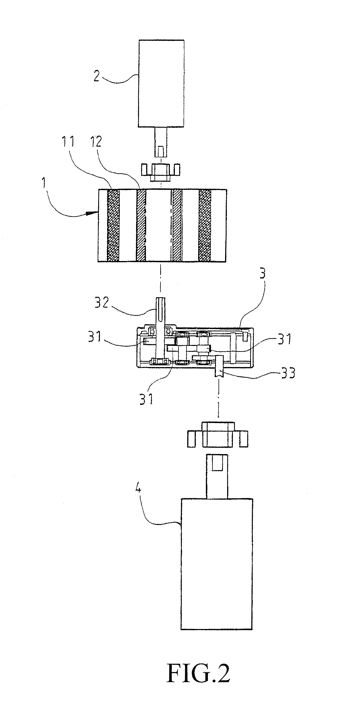
[0004]In accordance with the present invention, a magnetic force based automatic power generation device is provided, comprising a ring body, which has an inner circumference along which spaced permanent magnets are arranged and an outer circumference along which spaced electric magnets are arranged. A driving element is coupled to a top of the ring body. A speed reduction device is coupled to a bottom of the ring body. The speed reduction device is coupled to a power generation element. By starting the ring body by means of the electric magnets and the permanent magnets, the ring body is allowed to be continuously driven by alternating magnetic attractive and repulsive forces induced between magnetic poles of the permanent magnets and the electric magnets and a driving force generated by the driving element for fast rotation, which in turn drives the speed reduction device and the power generation element, so that the power generation device is caused to generate electric power, wherein a small fraction of the power so generated is applied back to the driving element to maintain the rotation of the ring body and a major portion of the power generated is supplied from the power accumulator to an external electric appliance to be consumed thereby so as to realize power generation of low energy consumption and high efficiency.

Problems solved by technology

With continuous consumption of the energy resources of the Earth, energy crises continuously emerge.
Up to date, this idea never succeeds and no practical perpetual machine has been developed and created.
One of the reasons is that there is no way to maintain constant rotation or operation of the perpetual machine without intervention of external forces and thus, the perpetual-machine power generation never becomes a useful and new substitute energy source.

Method used


Image

  • Magnetic force based automatic power generation device
  • Magnetic force based automatic power generation device
  • Magnetic force based automatic power generation device

Examples


Embodiment Construction

[0013]The following descriptions are exemplary embodiments only, and are not intended to limit the scope, applicability or configuration of the invention in any way. Rather, the following description provides a convenient illustration for implementing exemplary embodiments of the invention. Various changes to the described embodiments may be made in the function and arrangement of the elements described without departing from the scope of the invention as set forth in the appended claims.

[0014]Referring to FIGS. 1 and 2, which respectively show a schematic view of the present invention in an assembled form and a schematic exploded view of the present invention, and FIG. 3, which shows a schematic view of a ring body of the present invention, as shown in the drawings, the present invention comprises a ring body 1 that comprises a plurality of permanent magnets 11 arranged in a spaced manner along an inner circumference thereof and a plurality of electric magnets 12 arranged in a spac...


PUM


Abstract

A magnetic force based automatic power generation device includes a ring body, which has an inner circumference along which spaced permanent magnets are arranged and an outer circumference along which spaced electric magnets are arranged. A driving element is coupled to a top of the ring body. A speed reduction device is coupled to a bottom of the ring body. The speed reduction device is coupled to a power generation element. By starting the ring body by means of the electric magnets and the permanent magnets, the ring body is allowed to be continuously driven by alternating magnetic attractive and repulsive forces induced between magnetic poles of the permanent magnets and the electric magnets and a driving force generated by the driving element for fast rotation, which in turn drives the speed reduction device and the power generation element, so that the power generation device is caused to generate electricity.

Description

(a) TECHNICAL FIELD OF THE INVENTION[0001]The present invention generally relates to a magnetic force based automatic power generation device, and more particularly to a magnetic force based automatic power generation device that realizes high efficiency power generation through low energy consumption.(b) DESCRIPTION OF THE PRIOR ART[0002]With continuous consumption of the energy resources of the Earth, energy crises continuously emerge. For this reason, most countries of the world are spending a great amount of labors and resources in the development of new energies and substitute energies. One of the solutions that is commonly referred to is perpetual-machine power generation. Up to date, this idea never succeeds and no practical perpetual machine has been developed and created. One of the reasons is that there is no way to maintain constant rotation or operation of the perpetual machine without intervention of external forces and thus, the perpetual-machine power generation never...

Claims


Application Information

Patent Timeline
Patent Type & Authority Applications(United States)
IPC IPC(8): H02K47/14H02K53/00
CPCH02K53/00
Inventor LEE, CHIU-FA
Owner LEE CHIU FA
Learn More