
Sensing And Control Device

a technology of sensing and control device, applied in the direction of optical radiation measurement, instruments, service pipe system, etc., can solve the problems of complex valves, relatively high cost, and complicated construction

Inactive Publication Date: 2011-04-21
ALFA LAVAL CORP AB
View PDF8 Cites 6 Cited by
  • Summary
  • Abstract
  • Description
  • Claims
  • Application Information

AI Technical Summary

Benefits of technology

The present invention provides an actuator rod position indication device that can reliably show the position of the actuator and the valve closure member in a valve construction.

Problems solved by technology

These valves are very complex and are therefore often relatively expensive to buy and also to install in that they need to be calibrated very precisely in order to provide the correct position.
Furthermore, it may also be possible to deduct a position in between the open and closed positions, but this indication is uncertain in that there is not grading of the scale between open and closed.
This construction, however, is more complicated in that it in addition to mechanical means for indicating also comprises an electronic circuitry whereby it is possible to supply feedback to a control system.
The device according to U.S. Pat. No. 6,242,909 has a higher degree of accuracy but also a very high degree of complicity in its construction.
This may cause two drawbacks, one of which is the fact that it is very difficult to fit the indicating device to the valve construction afterwards, i.e. if the valve construction is not manufactured with the indicating device as an integrated part of the device.
Furthermore, mechanical couplings tend to wear which may give rise to failure such that uncertainties relating to the actual position of the valve closure member due to failure in the connection between the valve stein / actuator and the indicating device may give rise to the indicating device providing the wrong information.

Method used


Image

  • Sensing And Control Device
  • Sensing And Control Device
  • Sensing And Control Device

Examples


Embodiment Construction

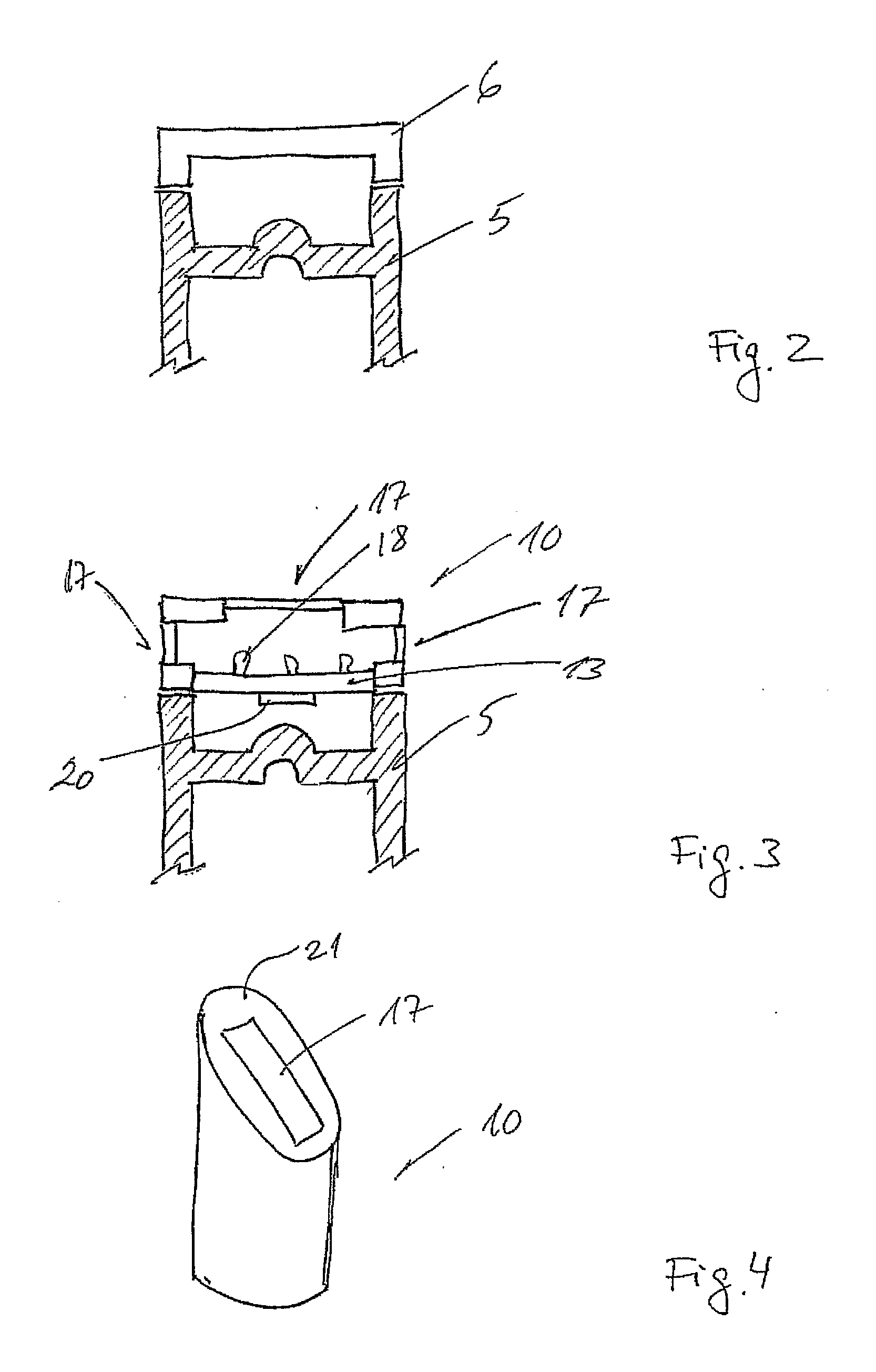
[0012]The present invention consequently discloses an actuator rod position indication device, where a unit having a separate enclosing housing on one surface of said housing has mounted a magnetic field sensor, such that a magnet provided on an actuator rod's free end will be moved substantially linearly closer to and further from said sensor during operation of the actuator, where the sensor detects the magnetic field strength between the magnet on the actuator rod and the sensor and uses this information as input in a processor, comprising a storage, in which storage pre-defined activation values are stored, such that when the input corresponds to one of the stored values, an output specific to that value is generated.

[0013]By relying on the strength of a magnetic field created between the sensor and a magnet arranged at the actuator rod's free end, there is no physical connection between the sensor and thereby the indicating device and the valve construction as such. This provid...


PUM


Abstract

An actuator rod position indication device is described, where a unit having a separate enclosing housing on one surface of said housing has mounted a magnetic field sensor, such that a magnet provided on an actuator rod's free end will be moved substantially linearly closer to and further from said sensor during operation of the actuator, where the sensor detects the magnetic field strength between the magnet on the actuator rod and the sensor and uses this information as input in a processor, comprising a storage, in which storage pre-defined activation values are stored, such that when the input corresponds to one of the stored values, an output specific to that value is generated.

Description

FIELD OF THE INVENTION[0001]The present invention relates to a sensing and control device for indicating an actuator rod position as well as a valve construction incorporating such a device.BACKGROUND OF THE INVENTION[0002]In the art there are a number of automatic valves which are supplied with indication and control units such that the unit may both indicate by a visible signal, for example by means of light or an acoustic signal, the condition of the valve as well as be provided with means for supplying feed-back to a central control unit.[0003]Examples of such sensing and control devices are available from the Alfa Laval Corporation under the brand names Think Top or Indi Top.[0004]Most of these devices are very reliable and accurate and are extremely useful for indicating complex valve movements, for example indicating the valve's closure member's exact position. These valves are very complex and are therefore often relatively expensive to buy and also to install in that they n...

Claims


Application Information

Patent Timeline
Patent Type & Authority Applications(United States)
IPC IPC(8): G01J1/00G01R33/02H05B37/02F16K37/00
CPCG01R33/072Y10T137/8225
Inventor ANDERSEN, JENS CHRISTIAN FOLKMARMADSEN, KARSTEN SCHACKREHHOFF, KENNETH
Owner ALFA LAVAL CORP AB
Learn More