
Knowledge-based driver apparatus for high lumen maintenance and end-of-life adaptation

a driver apparatus and knowledge-based technology, applied in the direction of electric variable regulation, process and machine control, instruments, etc., can solve the problems of decrepit illumination provided by the device, decrepit lumen output of the state light source, and decrepit lumen output of the device, so as to facilitate constant lumen operation, cost and accuracy

Active Publication Date: 2011-04-21
GE LIGHTING SOLUTIONS LLC
View PDF11 Cites 38 Cited by
  • Summary
  • Abstract
  • Description
  • Claims
  • Application Information

AI Technical Summary

Benefits of technology

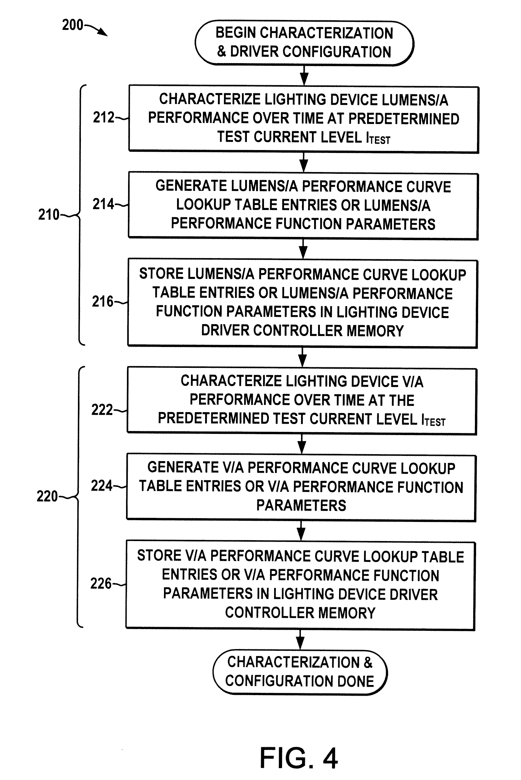
[0003]The controller is further operative in a test mode to implement knowledge-based adaptation of the normal mode operating current setpoint. In certain embodiments, the controller is configured to enter the test mode periodically, and the test mode may also be entered based on certain events. In the test mode, the controller provides a test mode current setpoint to the power source to drive the light source at a corresponding predetermined test current level and receives a voltage feedback value from the power source. From the voltage feedback, the controller determines the estimated degradation of the light source using the V / A performance characterization, and updates the current setpoint based on the estimated degradation using the L / A performance characterization. In this manner, the controller adapts the constant current output of the power source to conform to the lumen output depreciation aging characteristics of the solid-state lighting device, and may thus facilitate constant lumen operation without the need for external optical sensing and feedback components and the associated cost and accuracy problems.

Problems solved by technology

Many solid-state light sources suffer from lumen output depreciation, where the illumination provided by the device diminishes over time, even if driven at a constant current level.
These devices also suffer degraded performance as the light source nears its end-of-life.
However, such optical feedback systems increase the package size and add cost to the system, and the mechanical location of the optical sensor is critical to provide accurate light output measurement while avoiding stray light and other ancillary problems.

Method used


Image

  • Knowledge-based driver apparatus for high lumen maintenance and end-of-life adaptation
  • Knowledge-based driver apparatus for high lumen maintenance and end-of-life adaptation
  • Knowledge-based driver apparatus for high lumen maintenance and end-of-life adaptation

Examples


Embodiment Construction

[0014]Referring now to the drawings where like reference numerals are used to refer to like elements throughout, and wherein the various features are not necessarily drawn to scale, FIG. 1 illustrates a driver apparatus 100 for powering a solid-state light source 108, including a constant current power source 110, a controller 120, and a memory 130. The constant current power source 110 can be any suitable power conversion circuitry with an input 104 for receiving input electrical power and an output 106 coupleable to one or more solid-state light sources 108. While illustrated as driving a single light source 108, the driver 100 can be coupled to any number of solid-state light sources 108 in series and / or parallel configurations, in which the power source output 106 provides electrical output current to drive the light source(s) 108 for illumination applications. The controller 120 is configured to provide one or more setpoints to the power source 110, including a current setpoint...


PUM


Abstract

A knowledge-based driver is provided for powering a solid-state light source with a constant current, including a memory that stores lumens per amp and volts per amp performance characterizations of the light source over time, and a controller that operates in a test mode to estimate the light source degradation based on voltage feedback obtained at a predetermined test current value, and to adjust the drive current in normal operating mode according to the estimated device degradation to implement constant lumens control without external optical feedback components.

Description

BACKGROUND OF THE DISCLOSURE[0001]The disclosed embodiments relate to solid-state light source drivers and driver controls for maintaining constant lumen output and end-of-life (EOL) adaptation. Lighting devices are employed in a variety of applications for illuminating buildings, roads, and in other area lighting applications, as well as in a variety of signage and optical display applications. These applications are generally driven by a need for controlled illumination levels that may vary according to customer adaptation of dimming levels and the like. Many solid-state light sources suffer from lumen output depreciation, where the illumination provided by the device diminishes over time, even if driven at a constant current level. These devices also suffer degraded performance as the light source nears its end-of-life. Previous techniques for addressing these problems include direct optical feedback using a photosensor to detect the light output of the device, with closed-loop c...

Claims


Application Information

Patent Timeline
IPC IPC(8): H05B41/36G08B21/00H05B44/00
CPCH05B33/0893H05B33/0854H05B45/58H05B45/10H05B47/20Y02B20/72
Inventor ROBERTS, BRUCE RICHARDAURONGZEB, DEEDERPAYNE, KEVIN CARR
Owner GE LIGHTING SOLUTIONS LLC
Learn More