
Circuit breaker having dual arc chamber

a circuit breaker and arc chamber technology, applied in the direction of circuit breaker contacts, circuit breaker switches, contact mechanisms, etc., can solve the problems of preventing the circuit from being used, affecting the use and forming undesirable electric arcs, so as to increase the interrupting capacity of the circuit breaker

Active Publication Date: 2011-04-07
SIEMENS IND INC
View PDF3 Cites 9 Cited by
  • Summary
  • Abstract
  • Description
  • Claims
  • Application Information

AI Technical Summary

Benefits of technology

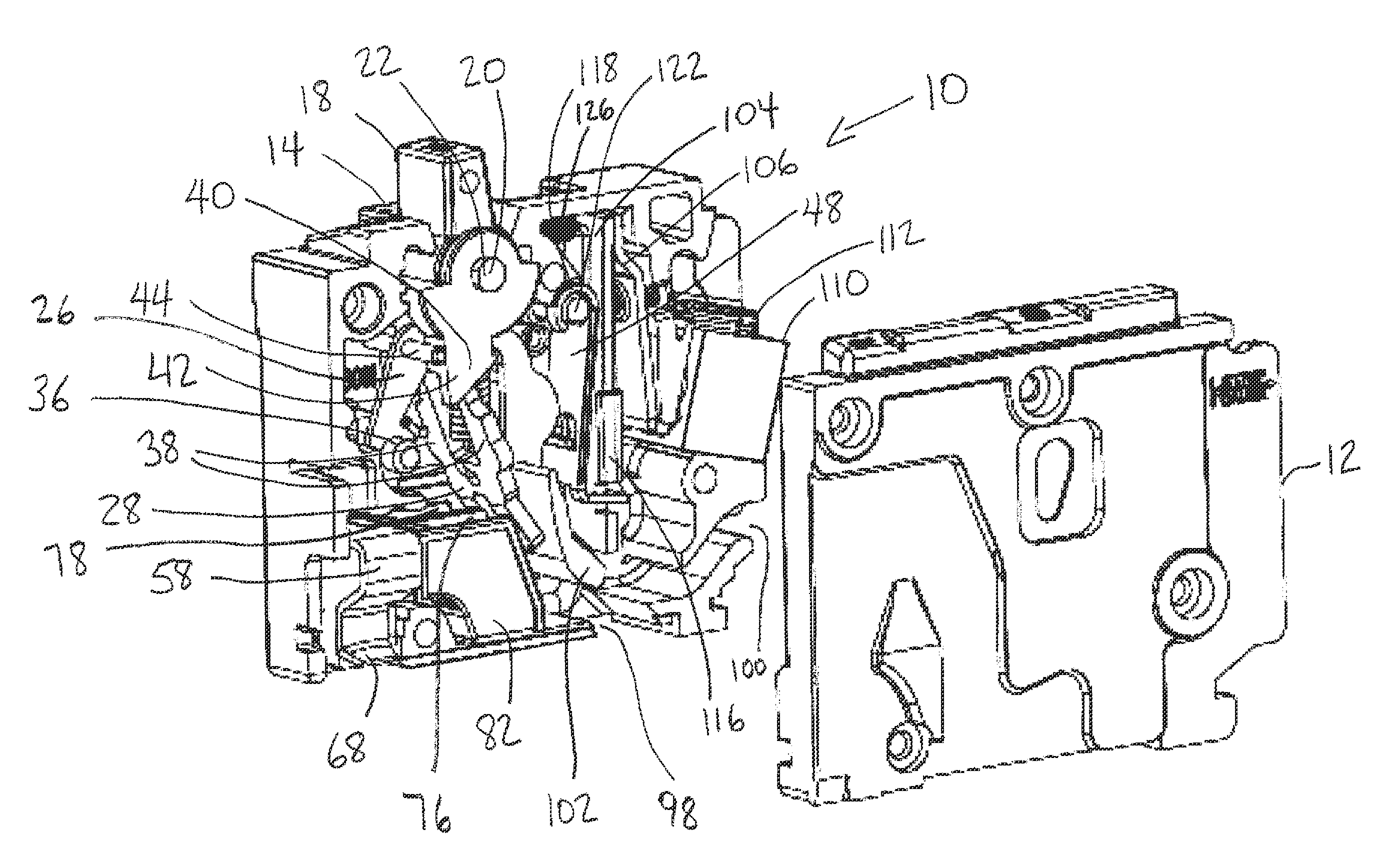
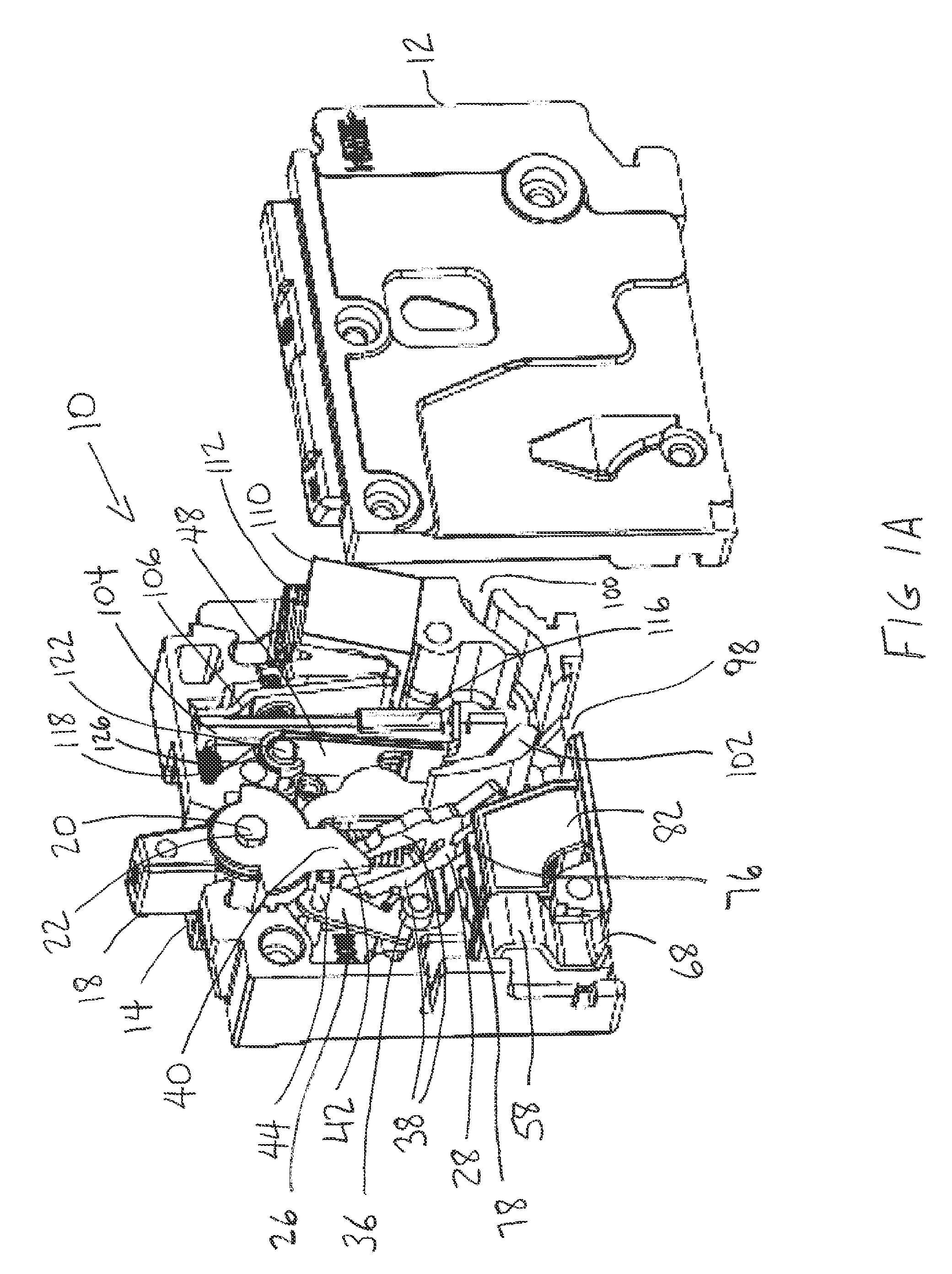
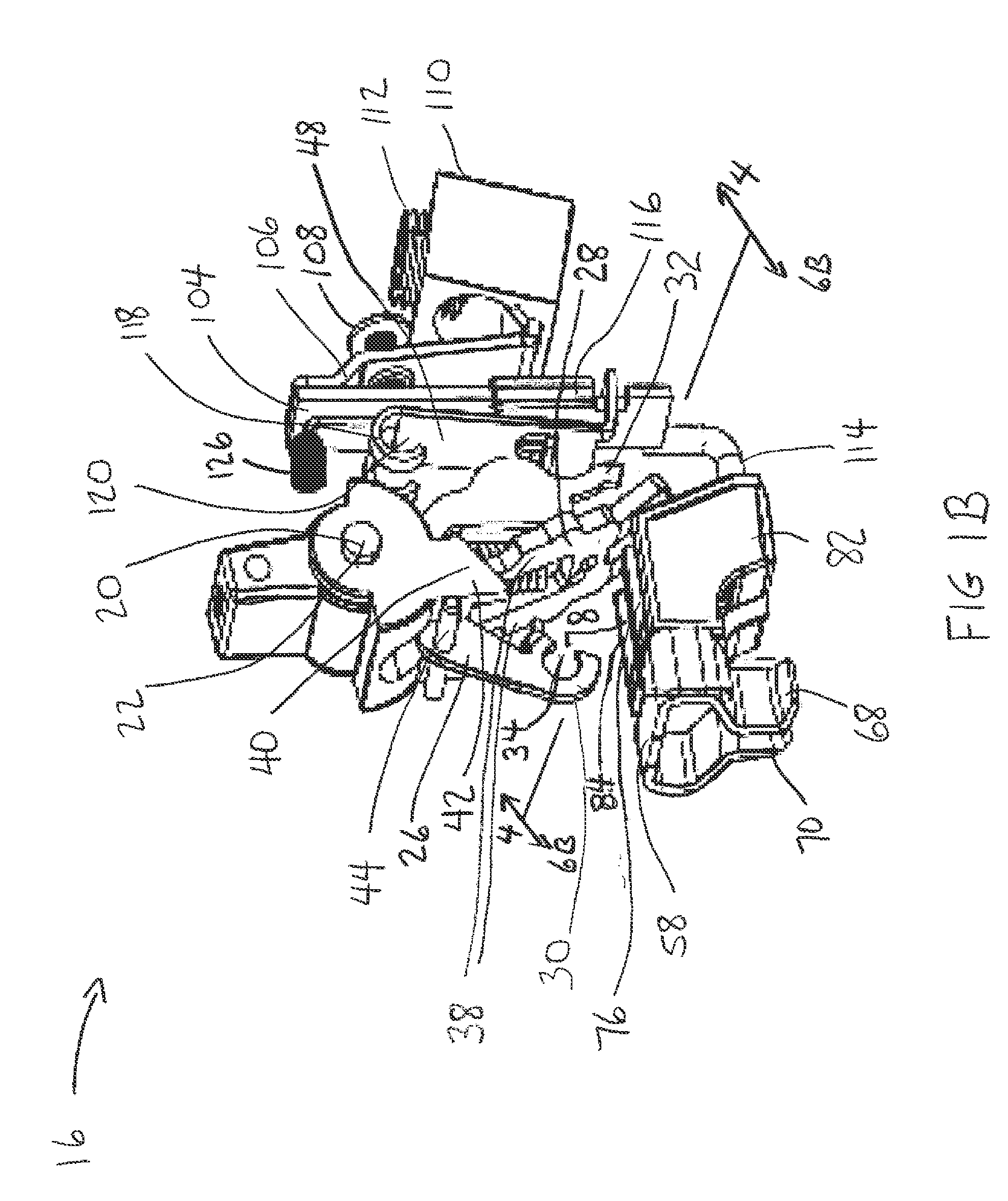
[0008]When a fault is detected in the electrical circuit and the first and second contact pairs are separated by an operating mechanism, respective first and second air gaps are formed. The circuit breaker also includes first and second arc chambers which are associated with the first and second contact pairs, respectively, for quenching arcs generated in the first and second air gaps. Due to the series arrangement of the circuit breaker components, the first and second air gaps form an effective air gap whose size is the sum of said first and second air gaps thereby increasing an interrupting capacity for the circuit breaker.

Problems solved by technology

When a fault condition is detected, the contacts are automatically opened, thus interrupting the circuit and disengaging the circuit from a power supply.
An undesirable electric arc is formed when the circuit is interrupted.
The arc may cause erosion of the contacts, thus hindering further use of the circuit breaker.
If the arc is not extinguished quickly, pressure from the ionized gases could cause the circuit breaker to rupture.
In particular, the interrupting capacity of the circuit breaker increases as the size of the air gap increases.
However, increasing the size of the air gap in a conventional circuit breaker also requires an increase in the overall size of the circuit breaker itself.
This is difficult to achieve since several applications for circuit breakers, such as circuit breakers used in the residential market, impose size constraints with respect to overall circuit breaker size.
Therefore, an increase in the air gap is difficult to achieve in conventional circuit breakers due to limitations on package size, thus making it difficult to increase the interrupting capacity or to improve other performance characteristics of the circuit breaker.

Method used


Image

  • Circuit breaker having dual arc chamber
  • Circuit breaker having dual arc chamber
  • Circuit breaker having dual arc chamber

Examples


Embodiment Construction

[0020]Before any embodiments of the invention are explained in detail, it is to be understood that the invention is not limited in its application to the details of construction and the arrangement of components set forth in the following description or illustrated in the following drawings. The invention is capable of other embodiments and of being practiced or of being carried out in various ways. Also, it is to be understood that the phraseology and terminology used herein is for the purpose of description and should not be regarded as limiting. The use of “including,”“comprising,” or “having” and variations thereof herein is meant to encompass the items listed thereafter and equivalents thereof as well as additional items. Unless specified or limited otherwise, the terms “mounted,”“connected,”“supported,” and “coupled” and variations thereof are used broadly and encompass direct and indirect mountings, connections, supports, and couplings. Further, “connected” and “coupled” are ...


PUM


Abstract

A circuit breaker which includes first and second contact pairs and a contact arm arranged in series. A first arm contact and a first terminal contact from a first line terminal form a first contact pair. A second arm contact and a second terminal contact from a second line terminal contact form a second contact pair. The first contact pair, contact arm and second contact pair are connected in a series arrangement in which the air gaps formed when the first and second contact pairs are separated combine to form an effective air gap which is double in size and thus increases an interrupting capacity of the circuit breaker. An arc chamber is associated with the first and second contact pairs for extinguishing an arc formed in the air gaps. The first and second contact pairs may also be arranged in a parallel configuration for increasing an amperage rating of the circuit breaker.

Description

CROSS REFERENCE TO RELATED APPLICATIONS[0001]This application claims the benefit under 35 U.S.C. §119(e) of U.S. Provisional Application No. 61 / 248,704 entitled DUAL ARC CHAMBERS AND H CONTACT ARM SYSTEM, filed on Oct. 5, 2009 which is incorporated herein by reference in its entirety and to which this application claims the benefit of priority.FIELD OF THE INVENTION[0002]This invention relates to circuit breakers, and more particularly, to a circuit breaker having first and second contact pairs and a contact arm electrically arranged in series and first and second arc chambers associated with the first and second contact pair, respectively, for increasing an interrupting capacity of the circuit breaker.BACKGROUND OF THE INVENTION[0003]A circuit breaker is used to protect an electrical circuit from damage caused by a persistent overcurrent condition or a very high current produced by a short circuit. During normal operation, a pair of contacts located within the circuit breaker are k...

Claims


Application Information

Patent Timeline
Patent Type & Authority Applications(United States)
IPC IPC(8): H01H33/02
CPCH01H9/40H01H73/18H01H73/045H01H73/04
Inventor CHEN, HAINAVARRE, LARRYMALACARA, HECTOR
Owner SIEMENS IND INC
Learn More