
Image processing apparatus, image processing method, and storage medium

a technology of image processing apparatus and image processing method, which is applied in the direction of geometric image transformation, instruments, computing, etc., can solve the problems of image edge dimming, fine feeling of magnified image fade, and increase the noise quantity of magnified imag

Active Publication Date: 2011-03-31
CASIO COMPUTER CO LTD
View PDF3 Cites 9 Cited by
  • Summary
  • Abstract
  • Description
  • Claims
  • Application Information

AI Technical Summary

Benefits of technology

[0006]Accordingly, it is an object of the present invention to provide an image processing apparatus, an image processing method, and a storage medium that can properly achieve a change of a magnified image to a high definition image.
[0010]According to the first, second and third aspects of the present invention, it is possible to emphasize an image edge to properly achieve a change of a magnified image to a high definition image.

Problems solved by technology

If a magnification ratio becomes larger in the magnification method, however, an image edge becomes dim, or the noise quantity of a magnified image increases.
As a result, the magnification method has a problem in which the fine feeling of a magnified image fades.

Method used


Image

  • Image processing apparatus, image processing method, and storage medium
  • Image processing apparatus, image processing method, and storage medium
  • Image processing apparatus, image processing method, and storage medium

Examples


Embodiment Construction

[0016]In the following, a concrete embodiment of the present invention will be described with reference to the accompanying drawings. The scope of the invention is, however, not limited to the shown examples.

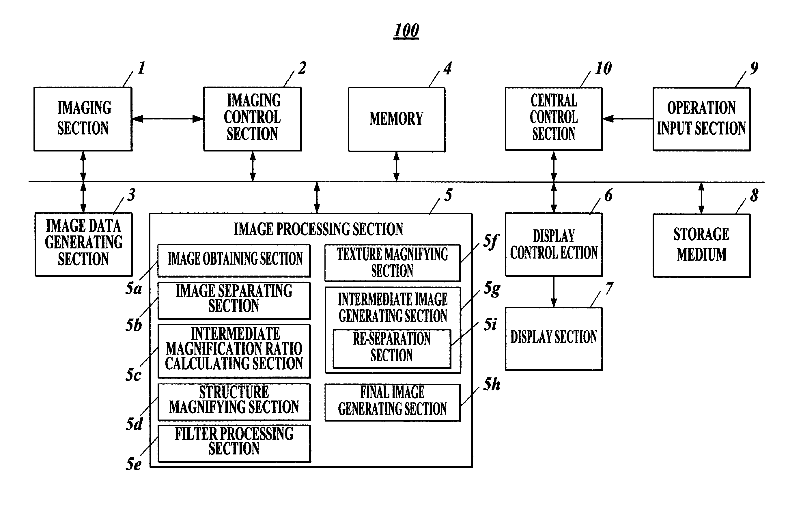
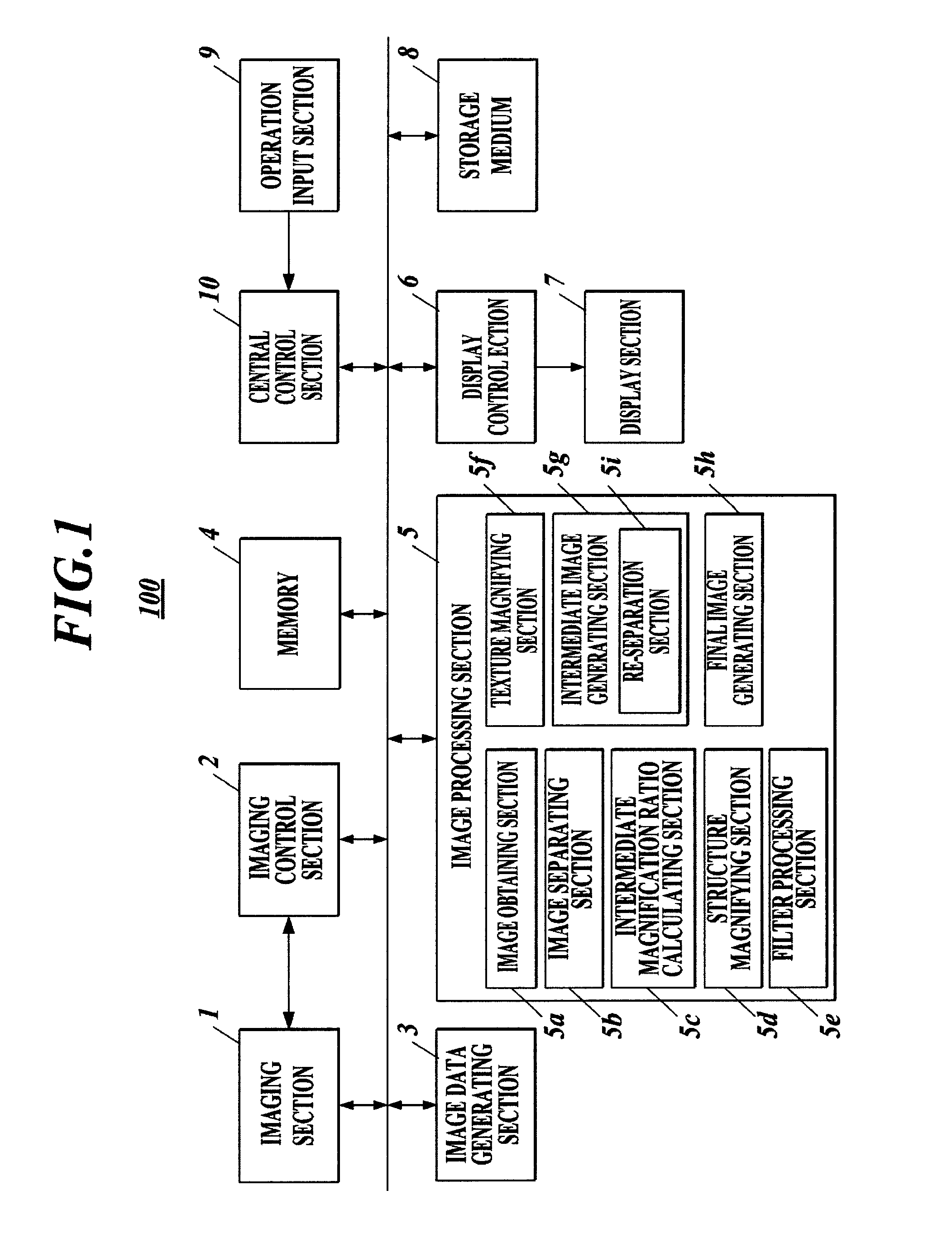
[0017]FIG. 1 is a block diagram showing the schematic configuration of an imaging apparatus 100 of an embodiment to which the present invention is applied.

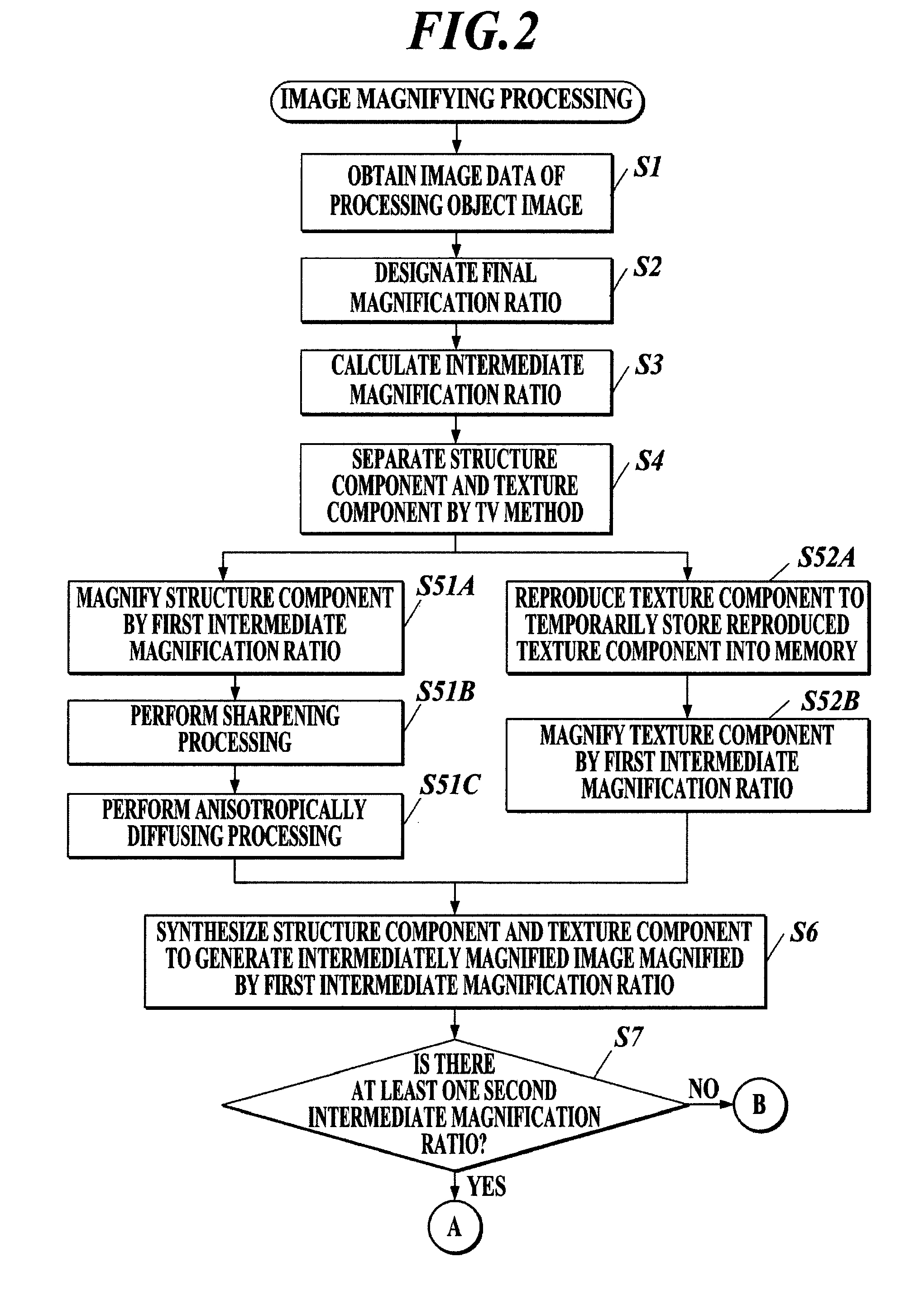
[0018]The imaging apparatus 100 of the present embodiment magnifies each of a structure component (e.g. structure component Gs; see FIG. 4B) and a texture component (e.g. texture component Gt; see FIG. 4C), both separated from an original image (e.g. original image Go; see FIG. 4A) by an intermediate magnification ratio, and synthesizes the structure component and the texture component after the magnification to generate an intermediately magnified image. Then, the imaging apparatus 100 magnifies the structure component separated from the intermediately magnified image to generate a finally magnified structure component which ...


PUM


Abstract

An imaging apparatus includes an intermediate image generating section to generate a second structure component and a second texture component by magnifying each of a first structure component and a first texture component separated from an original image by an intermediate magnification ratio and to synthesize the second structure component and the second texture component to generate an intermediately magnified image, and a final image generating section to generate a finally magnified image by synthesizing a finally magnified structure component generated by magnifying a third structure component separated from the intermediately magnified image by a final magnification ratio, and a finally magnified texture component generated by magnifying the first texture component by the final magnification ratio.

Description

BACKGROUND OF THE INVENTION[0001]1. Field of the Invention[0002]The present invention relates to an image processing apparatus, an image processing method using the image processing apparatus, and a storage medium.[0003]2. Description of the Related Art[0004]An image processing apparatus to change a magnified image to a high definition image by using a Total Variation (TV) Method in image magnifying processing in place of interpolation methods, such as a nearest neighbor method and a bicubic method, has conventionally been known (e.g. Japanese Patent Application Laid-Open Publication No. 2007-317109).[0005]The aforesaid magnification method using the TV method can achieve a change of a magnified image to a high definition image better than the interpolation methods, such as the nearest neighbor method and the bicubic method. If a magnification ratio becomes larger in the magnification method, however, an image edge becomes dim, or the noise quantity of a magnified image increases. A...

Claims


Application Information

Patent Timeline
Patent Type & Authority Applications(United States)
IPC IPC(8): G06K9/32
CPCG06T3/40
Inventor MIYAMOTO, NAOTOMO
Owner CASIO COMPUTER CO LTD
Learn More