
Ring network system and communication path control method

a technology communication path, applied in the field of ring network system, can solve problems such as system administrators overburdening users

Inactive Publication Date: 2011-03-31
HITACHI LTD
View PDF2 Cites 7 Cited by
  • Summary
  • Abstract
  • Description
  • Claims
  • Application Information

AI Technical Summary

Benefits of technology

[0012]The present invention has been made in consideration of the foregoing. It is therefore an object of the present invention to provide an Ethernet ring network system and a communication path control method capable of positioning a ring redundant link without burdening users.
[0015]The invention can position a ring redundant link without burdening users.

Problems solved by technology

Such configuration or changeover requires recognition of the traffic for each link and may overburden users such as system administrators.

Method used


Image

  • Ring network system and communication path control method
  • Ring network system and communication path control method
  • Ring network system and communication path control method

Examples


Embodiment Construction

[0025]An embodiment of the ring network system and the communication path control method according to the invention will be described in further detail with reference to the accompanying drawings.

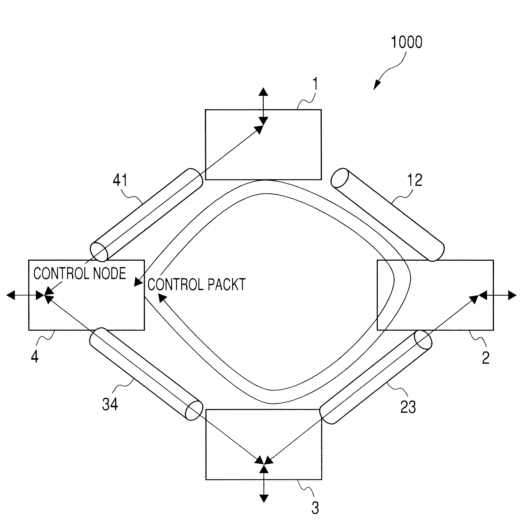
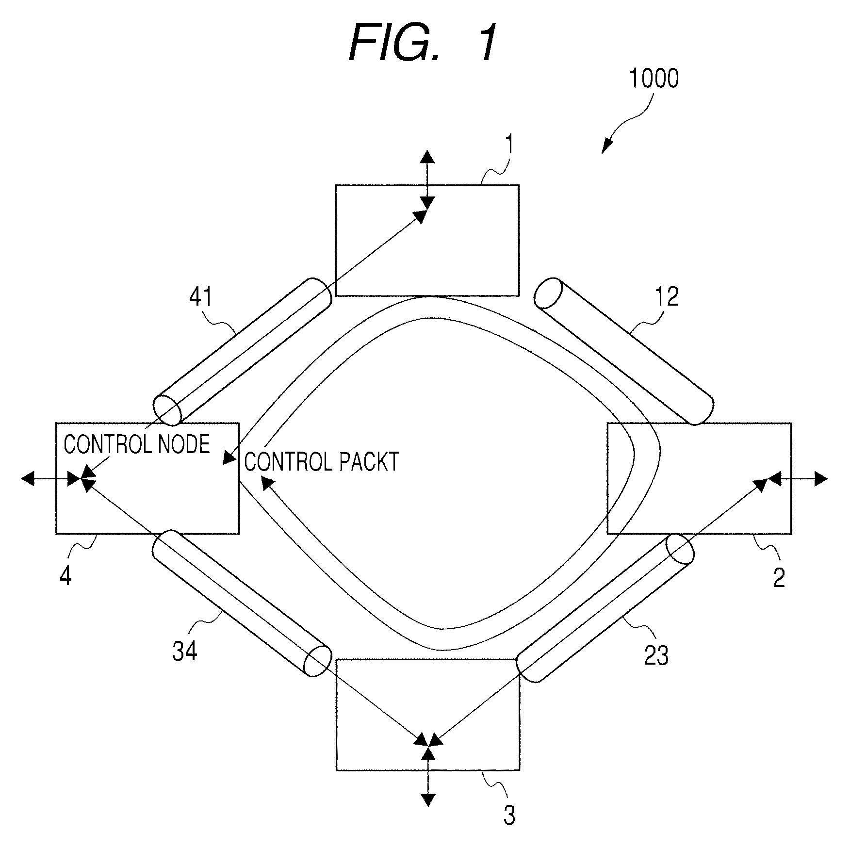
[0026]FIG. 1 shows a configuration of an Ethernet ring network system 1000 according to the embodiment of the invention. As shown in FIG. 1, the Ethernet ring network system 100 includes non-control Ethernet switches 1 through 3, a control Ethernet switch 4, and links 12, 23, 34, and 41 for connection between the non-control Ethernet switches and the control Ethernet switch.

[0027]In the following description, the non-control Ethernet switch may be referred to as a non-control node. The control Ethernet switch may be referred to as a control node. When a redundant communication path is used, the non-control node may be referred to as a redundant node as will be described later. The link 12 is equivalent to a LAN (Local Area Network) line, for example.

[0028]The non-control nodes 1 through 3 i...


PUM


Abstract

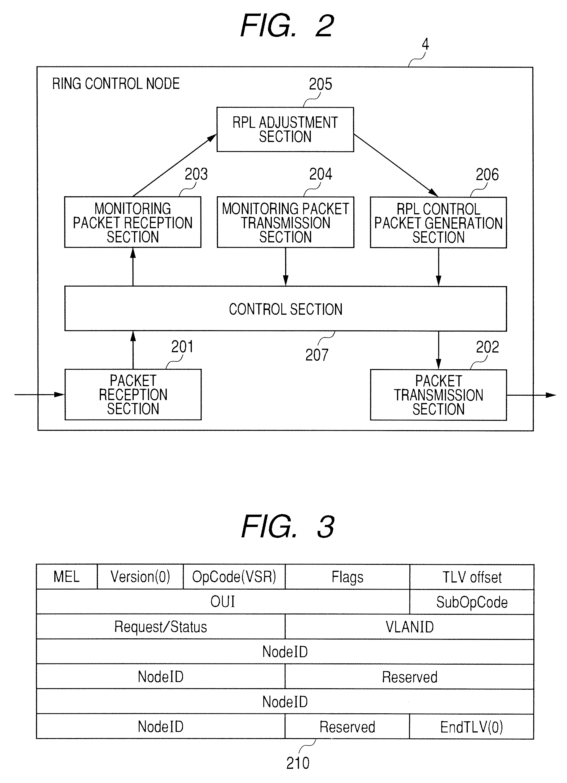
A control node includes: a monitoring packet transmission section for transmitting a monitoring packet; a monitoring packet reception section for receiving a monitoring packet; an adjustment section for selecting a redundant node from a non-control nodes; a packet generation section for generating a setup packet for specifying the redundant node out of the non-control nodes in accordance with information about the redundant node selected by the adjustment section; and a packet transmission section for transmitting the setup packet to the non-control node. The non-control node includes a control section that acquires information about the traffic upon receiving the monitoring packet, transmits a monitoring packet after acquisition of the traffic, and specifies the non-control node as the redundant node based on information about the redundant node contained in the setup packet upon receiving the setup packet.

Description

CLAIM OF PRIORITY[0001]The present application claims priority from Japanese application serial no. JP2009-224930, filed on Sep. 29, 2009, the content of which is hereby incorporated by reference into this application.BACKGROUND OF THE INVENTION[0002]1. Field of the Invention[0003]The present invention relates to a ring network system for solving redundancy of Ethernet (registered trademark) communication paths. More particularly, the invention relates to a ring network system and a communication path control method for traffic dispersion on a VLAN (Virtual Local Area Network) basis.[0004]2. Description of Related Art[0005]A conventional Ethernet system often uses a ring network topology containing annularly connected multiple Ethernet switches so as to make communication paths redundant.[0006]The ring network topology is provided with two redundant paths according to clockwise and counterclockwise rotations along the ring. For example, let us suppose that an error occurs at a given...

Claims


Application Information

Patent Timeline
IPC IPC(8): H04L12/26H04L12/42
CPCH04L12/4641H04L12/437
Inventor SAIGUSA, YASUNORISHIMIZU, SATOSHINAKAGAWA, TAKAYUKIMOTOYAMA, SHINYA
Owner HITACHI LTD
Learn More