
Walking cane

a walking cane and cane technology, applied in the field of walking aids, can solve the problems of increased pain, increased pain, and increased pain of walking, and achieve the effect of preventing flexing and being durable enough

Active Publication Date: 2011-03-31
KINETICANE
View PDF45 Cites 6 Cited by
  • Summary
  • Abstract
  • Description
  • Claims
  • Application Information

AI Technical Summary

Benefits of technology

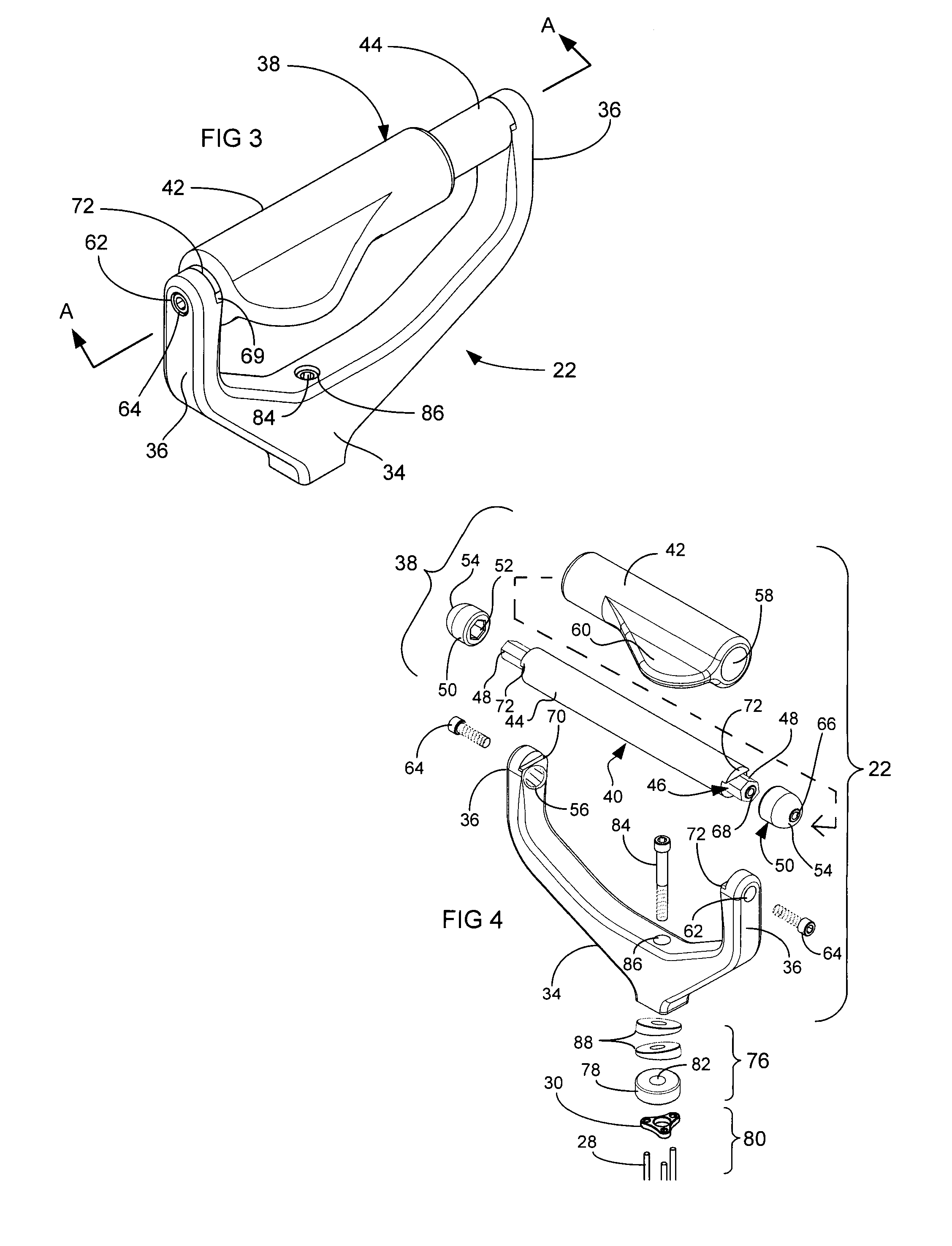
[0006]The present invention overcomes the deficiencies of the prior art in several of its embodiments. It is therefore an object of the present invention to provide a walking cane or crutch including a non-stationary, shock absorbing handle assembly to assist in relieving hand, wrist and arm strains. In one embodiment, the handle assembly comprises a closed configuration having opposing first and second upright posts. The posts carry a grip biased by first and second pliable mounts held in place under tension by a fastening mechanism. The mounts act as shock absorbers and permit the grip to have limited omni-directional movement relative to each post.
[0007]In another embodiment, the handle assembly comprises an open configuration having a generally upright post, a grip connectable substantially orthogonal to the post, and a pliable mount engageable with the post and the grip. A fastening mechanism secures the grip and the mount to the post, thereby biasing mount against the grip. The mount acts as a shock absorber and permits the grip to have limited omni-directional movement relative to the post.
[0008]In another embodiment, a pliable mount is positioned between the handle assembly and a vertical support. The mount acts as shock absorbers and permits the handle assembly to have limited omni-directional movement relative to the vertical support.
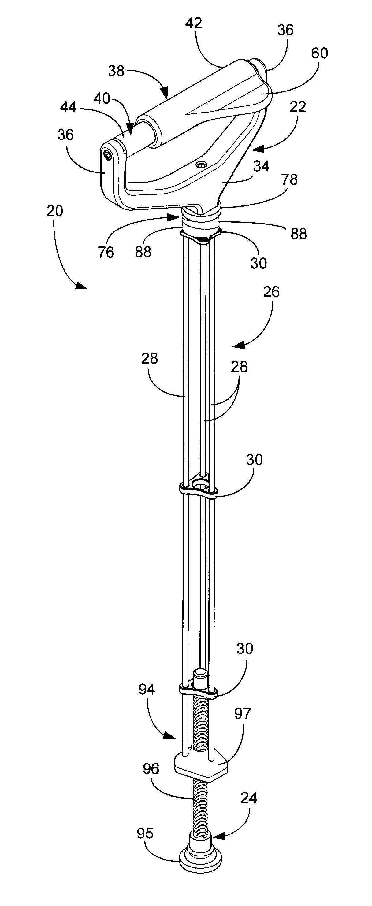
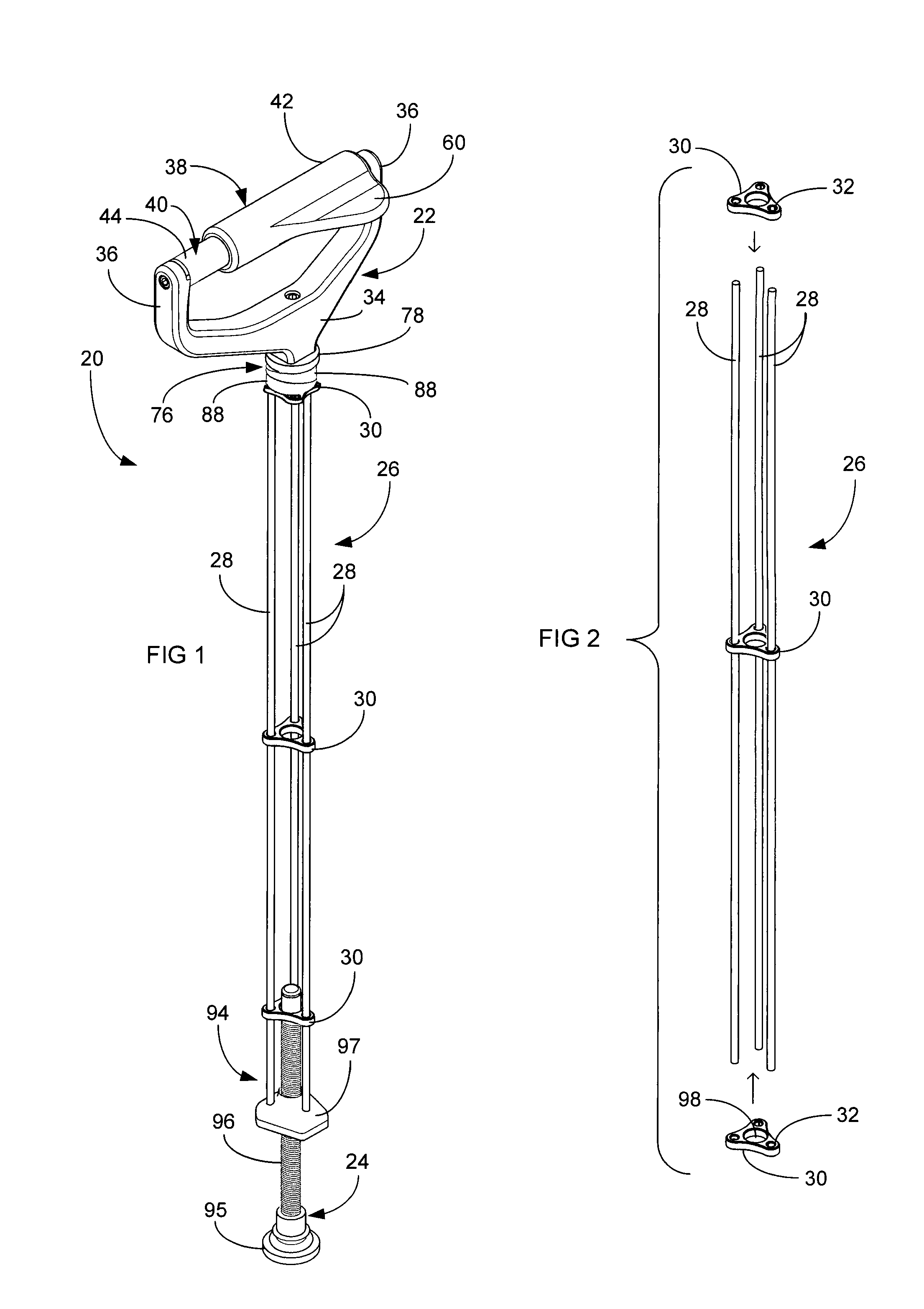
[0010]Another object of the present invention is to provide an extremely lightweight vertical support, durable enough to withstand the force of a person resting, leaning or using the cane as a means of support. In one embodiment, the vertical support includes three parallel elongated rods spaced apart from one another in a triangular position. Triangular brackets attach to the rods to prevent flexation thereof when a load is applied to the walking device.

Problems solved by technology

Without the aid of ambulatory devices, many individuals have a difficult, if not an impossible, time of moving one's self even within the confines of their own home.
Generally, though, conventional walking canes contain a fixed design which imposes excessive stress on the user's hands, wrists and triceps, resulting in associated shoulder and back strain caused by gait compensation.
Conventional cane shafts also have the deleterious effect of providing stiff repetitive shock to hands and arms as weight is applied to the cane, resulting in painful fatigue through frequent use.
Such a walking aid would diminish excessive stress applied to the hands and wrists during its use, thereby decreasing gait compensation to reduce the occurrence of shoulder and back strain.

Method used


Image

  • Walking cane
  • Walking cane
  • Walking cane

Examples


Embodiment Construction

[0025]A first embodiment of a walking cane according to the present invention is generally indicated at 20 in FIG. 1. While the present description uses the term cane throughout, it should be noted that that term is meant to include a multiplicity of walking aids or ambulatory devices, including crutches and walkers. The walking cane 20 generally includes a handle assembly 22 and a ground engaging assembly 24, each connected to a vertical support assembly 26. As illustrated in FIG. 2, the vertical support assembly 26 includes three elongated rods 28 spaced-apart in a preferably triangular fashion. Each rod 28 is preferably constructed from a light-weight, high tensile strength material, for example carbon fiber composite. However, similar suitable materials for the construction of the rods 28 are well within the scope of the present invention, including aluminum, magnesium, titanium, advanced high-strength steels, fiber-reinforced composites, and metal matrix composites. It has been...


PUM


Abstract

The present invention includes a walking cane having a handle assembly, a support assembly and foot member. The handle assembly includes first and second generally upright rigid posts. A shaft adaptable for grasping by a user's hand connects to each end of the posts. Pliable mounts dispose between the terminal ends of the shaft and each post. The mounts, biased against the shaft, permit omni-directional movement of the shaft relative to each post. The support assembly connects to the handle assembly and includes three parallel elongated rods spaced apart from one another in a triangular formation. The handle assembly can be adjusted relative to the support assembly by means of two cooperating shims. The foot member connects to the support assembly and contacts the ground. The cane provides a light-weight shaft and a shock absorbing handle assembly to assist in relieving hand, wrist and arm strains.

Description

CROSS-REFERENCE TO RELATED APPLICATION(S)[0001]This application claims the benefit of U.S. Provisional Patent Application No. 61 / 246,776 entitled WALKING CANE, filed on 29 Sep. 2009, which is hereby incorporated herein by reference.BACKGROUND OF INVENTION[0002]The present invention is generally directed at ambulatory devices. More particularly, the present invention is directed at a walking aid having improved ergonomics, strategic shock absorption properties, and a lightweight multi-structural shaft.[0003]Walking is an important function in everyday life, even over short distances. Without the aid of ambulatory devices, many individuals have a difficult, if not an impossible, time of moving one's self even within the confines of their own home. As of 2008, an estimated 12 million people in the United States reported at least some mobility difficulty. Many of these individuals include senior citizens, whose population is ever drastically increasing as “baby boomers” begin to enter t...

Claims


Application Information

Patent Timeline
IPC IPC(8): A45B9/00A45B9/04A45B9/02
CPCA45B9/02A45B2009/005A45B9/04
Inventor GOLDBERG, RONALD M.GOLDBERG, JOSEPH
Owner KINETICANE
Learn More