
Electrode and lead stability indexes and stability maps based on localization system data

a technology of localization system and stability index, applied in the field of electro-electrode-based investigation or therapy systems, can solve the problems of consuming precious resources, compromising the ability of devices to deliver therapy in an optimal manner, and mechanisms not guaranteeing stability

Inactive Publication Date: 2011-03-17
PACESETTER INC
View PDF12 Cites 21 Cited by
  • Summary
  • Abstract
  • Description
  • Claims
  • Application Information

AI Technical Summary

Benefits of technology

The patent describes a method for selecting an electrode in a patient for delivering therapy or sensing biological electrical activity. The method involves acquiring position information of the electrode over time, calculating a stability metric for the electrode, and comparing the stability metric to a threshold to determine if the electrode is stable for delivering therapy or sensing biological electrical activity. The method can be used with different types of electrodes and can help improve the accuracy and effectiveness of therapy or sensing procedures.

Problems solved by technology

Alternatively, if the lack of stability or the dislodgement is tolerated, a device's ability to delivery therapy in an optimal manner may be compromised (e.g., an electrode configuration for sensing may become unreliable to support an algorithm such as for automatic determination of capture threshold).
While many leads include anchoring mechanisms, such mechanisms do not guarantee stability.
As to the latter, data indicates that an unstable electrode is likely to trigger algorithms such as an automatic capture threshold determination algorithm, which, in turn, can consume precious resources (e.g., consider a battery as an implantable device's limited power supply).
While ICD and CRT have been mentioned, electrode and lead stability can be an issue with other investigations or procedures.

Method used


Image

  • Electrode and lead stability indexes and stability maps based on localization system data
  • Electrode and lead stability indexes and stability maps based on localization system data
  • Electrode and lead stability indexes and stability maps based on localization system data

Examples


Embodiment Construction

The following description includes the best mode presently contemplated for practicing the described implementations. This description is not to be taken in a limiting sense, but rather is made merely for the purpose of describing the general principles of the implementations. The scope of the described implementations should be ascertained with reference to the issued claims. In the description that follows, like numerals or reference designators are typically used to reference like parts or elements throughout.

Overview

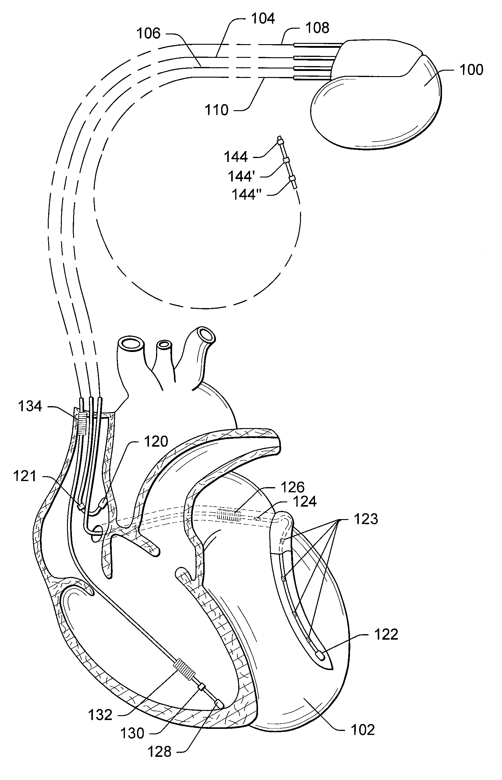
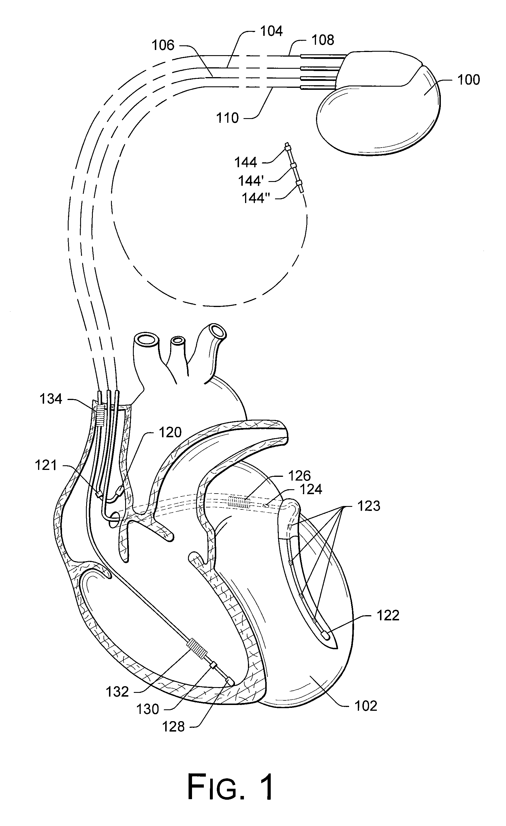
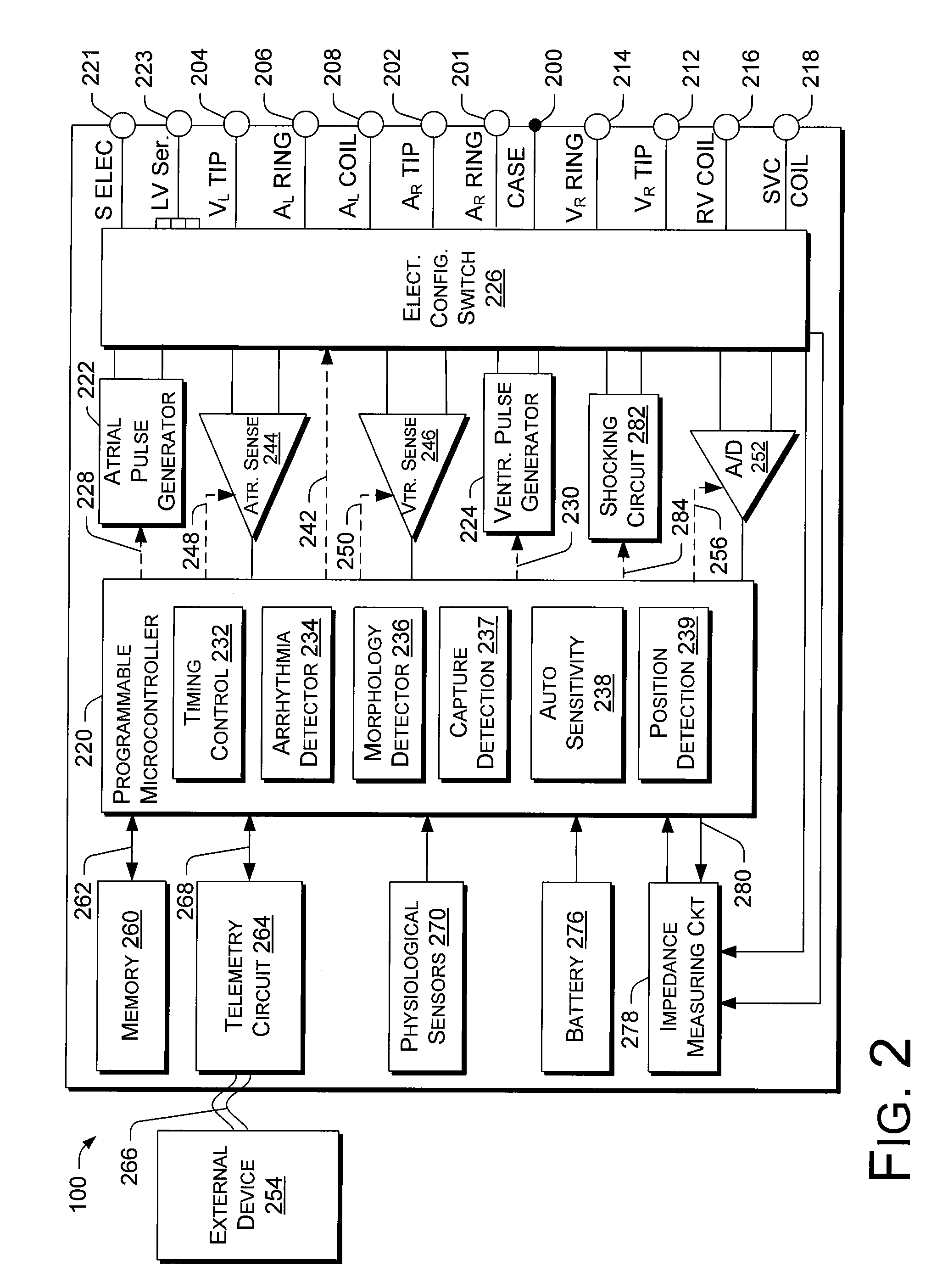
Various exemplary techniques described herein pertain to stability analysis of electrodes or lead in the body. For example, during an intraoperative procedure, a clinician may maneuver a catheter to various locations in one or more chambers or vessels of the heart and acquire position information sufficient to calculate one or more stability metrics. In various examples, acquisition of position information may occur for a chronic state, for example, sufficient to cal...


PUM


Abstract

A method includes selecting an electrode located in a patient wherein the electrode comprises a lead-based electrode; acquiring position information with respect to time for the electrode, during both loaded and unloaded conditions of the lead, where the acquiring uses the electrode for repeatedly measuring electrical potentials in an electrical localization field established in the patient; calculating a both loaded and unloaded stability metrics for the electrode based on the acquired position information with respect to time; and comparing the unloaded and loaded stability metrics to decide whether the electrode, as located in the patient, comprises a stable location for delivery of therapy.

Description

TECHNICAL FIELDSubject matter presented herein relates generally to electrode and lead-based investigation or therapy systems (e.g., cardiac pacing therapies, cardiac stimulation therapies, etc.). Various examples acquire position data using a localization system and, based on the acquired data, calculate stability metrics (e.g., as indexes or maps).BACKGROUNDVarious surgical procedures rely on placement of electrodes into the body (e.g., electrode devices, electrode-bearing leads or catheters, etc.). For example, a typical implantable cardiac defibrillator (ICD) includes a “can” for placement in a pectoral pocket and an electrode-bearing lead for placement into a chamber of the heart or a vein of the heart. In this example, an electrode of the can and an electrode of the lead can sense cardiac electrical activity indicative of fibrillation and respond (e.g., by control logic in the can) by delivering energy to defibrillate the heart. To ensure proper performance, whether for sensin...

Claims


Application Information

Patent Timeline
Patent Type & Authority Applications(United States)
IPC IPC(8): A61N1/00
CPCA61B5/015A61B5/042A61B5/061A61B5/1107A61B5/6846A61B5/6885A61B2562/043A61N1/36185A61N1/36521A61N1/3686A61N1/372A61N1/3962A61B5/6852A61B2017/00053A61N1/39622A61B5/283A61B5/29
Inventor ROSENBERG, STUARTNGUYEN, THAO THURYU, KYUNGMOONOREN, KJELLKEEL, ALLENHOU, WENBOYANG, MICHAEL
Owner PACESETTER INC
Learn More