Ink jet apparatus and method of reducing crosstalk

Active Publication Date: 2011-03-17
TOSHIBA TEC KK
View PDF7 Cites 16 Cited by
  • Summary
  • Abstract
  • Description
  • Claims
  • Application Information

AI Technical Summary

Benefits of technology

is to provide a technique of reducing crosstalk, which is generated when employing a share

Problems solved by technology

However, in the above-described conventional technique, since the pressure fluctuation which generates the crosstalk compensating for the change in ejection speed is restricted to a level where ink is not ejected from nozzles, it is difficult to obtain sufficient effects although changes in the volume and ejection speed due to the crosstalk can be reduced to a certain level.
In addition, in the above-described conventional technique, it is necessary to selectively supply to respective channels pulses for ejecting ink depending on the generation of dummy pulses and pulses with different voltages and a drive signal generating unit becomes complicated, so an inexpensive ink jet recording apparatus having high reliability cannot be provided.
Although this technique is highly effective from the point of view of the elimination of crosstalk, a driving signal generating unit is required to generate an arbitrary waveform and thus the drive circuit becomes complicated and an inexpensive ink jet recording apparatus having high reliability cannot be provided.
Accordingly, a drive circuit of the conventional ink jet head is required to selectively supply to respective channels a drive voltage for correcting crosstalk as well as a drive voltage for ink ejection and thus the drive circuit becomes complicated.

Method used


Image

  • Ink jet apparatus and method of reducing crosstalk
  • Ink jet apparatus and method of reducing crosstalk
  • Ink jet apparatus and method of reducing crosstalk

Examples


first embodiment

First, a first embodiment will be described.

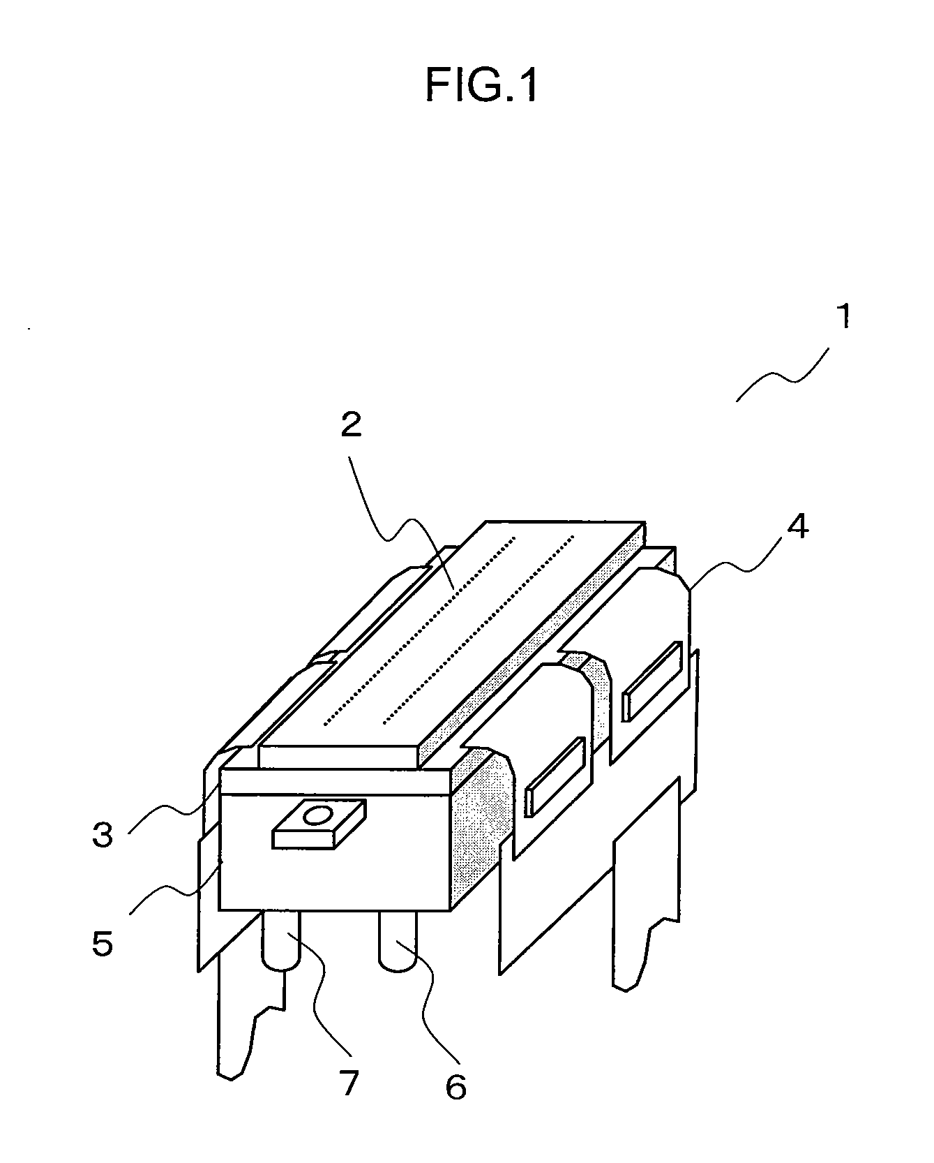
FIG. 1 is a perspective view of an ink jet head 1 of an ink jet recording apparatus according to the first embodiment.

The ink jet head 1 is provided with a head substrate 3 having nozzles 2 for ejecting ink, a driver IC 4 generating drive signals (drive signal generator) and a manifold 5 having an ink supply port 6 and an ink discharge port 7.

The ink jet head 1 ejects from the nozzles 2 the ink supplied from the ink supply port 6 in accordance with a drive signal generated by the driver IC 4. The ink which is not ejected from the nozzles 2 among the ink flowing from the ink supply port 6 is discharged from the ink discharge port 7.

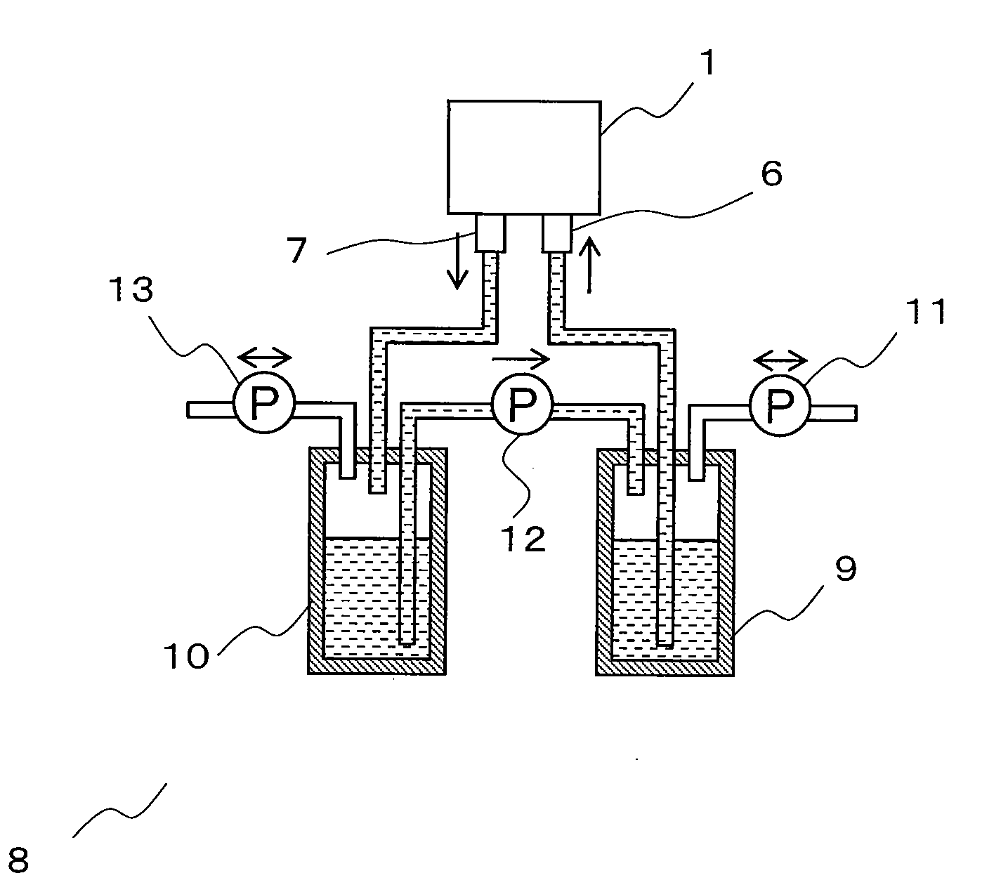
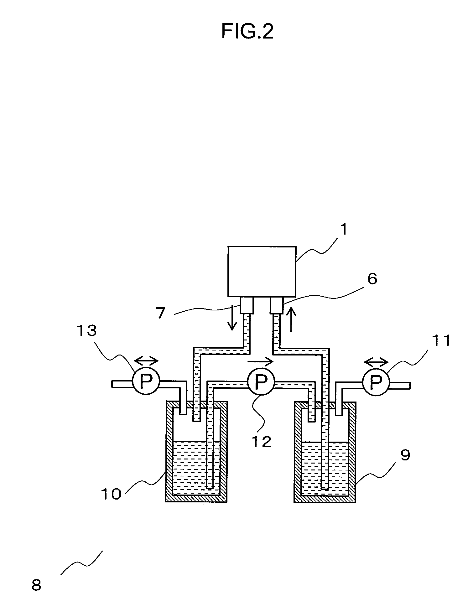
FIG. 2 is a schematic diagram of an ink supply apparatus 8 which is used in the ink jet recording apparatus according to the first embodiment. The ink supply apparatus 8 includes a supply-side ink tank 9, a discharge-side ink tank 10, a supply-side pressure adjustment pump 11, a transfer pump 12, a discharge-side...

second embodiment

Next, a second embodiment will be described. The second embodiment is a modified example of the above-described first embodiment. Hereinafter, the same reference numerals will be assigned to parts having the same functions as those of the above-described parts in the embodiment and descriptions thereof will be omitted.

FIG. 9 is a detail view showing drive signals S1 to S3 of the second embodiment. The polarization direction of actuators is the same as in the first embodiment.

Differences between the first embodiment and the second embodiment will be described. In the first embodiment, the drive signal S1 for ejecting ink is supplied to a channel which is to eject the ink. However, in the second embodiment, the drive signal S1 for ejecting ink is supplied to a channel adjacent to the channel which is to eject the ink.

In addition, in the first embodiment, the square waves of the drive signals S1 to S3 move in a positive logical manner which starts with the rising of the voltage and end...

third embodiment

The third embodiment is a modified example of the above-described embodiments. Hereinafter, the same reference numerals will be assigned to parts having the same functions as those of the above-described parts in the embodiments and descriptions thereof will be omitted.

FIG. 10 is a detail view of drive signals S1 to S3 in the third embodiment. The polarization direction of actuators in this embodiment is opposite to that of the first or second embodiment as shown in FIG. 11.

In the third embodiment, the drive signal S1 for ejecting ink is supplied to a channel adjacent to a channel which is to eject the ink. However, unlike the second embodiment, square waves of the drive signals S1 to S3 move in a positive logical manner.

However, as shown in FIG. 10(b), the movement of actuators is substantially the same as in the first embodiment.

Fourth Embodiment

Next, a fourth embodiment will be described.


PUM


Abstract

When ink is ejected from any one of a plurality of pressure chambers, an electric field pulse, which corresponds to an electric field pulse to be applied to a partition wall of the pressure chamber which is to eject the ink, and has at least one square wave, which is in a direction opposite to that of the electric field pulse and has a pulse width corresponding to the electric field pulse, is applied to a partition wall adjacent to the partition wall of the pressure chamber which is to eject the ink.

Description

CROSS-REFERENCE TO RELATED APPLICATION(S)This application is based upon and claims the benefit of priority from Japanese Patent Application No, 2009-213672, filed on Sep. 15, 2009; the entire contents of which are incorporated herein by reference.FIELDEmbodiments described in this specification relate to an ink jet technique of ejecting ink from a plurality of nozzles, and particularly, to a technique of reducing crosstalk which is generated when employing a shared-wall ink jet head.BACKGROUNDConventionally, ink jet heads employing a so-called “shared-wall head” system in which the partition walls of pressure chambers adjacent to each other serve as actuators are known. In the ink jet heads employing this system, pressure fluctuation, which is caused in the pressure chambers, deforms actuators and is spread to adjacent pressure chambers, and thus “crosstalk” is generated and variations are caused in the volume and speed of ink droplets which are ejected in accordance with an image p...

Claims


Application Information

Patent Timeline
IPC IPC(8): B41J29/38
CPCB41J2/04525B41J2/04541B41J2/04573B41J2/04581B41J2202/12B41J2/175B41J2/17596B41J2202/10B41J2/04588B41J2/04596
Inventor KUSUNOKI, RYUTARO
Owner TOSHIBA TEC KK
Why Eureka
Try Eureka