
Alternating current motor control system

a control system and alternating current technology, applied in the direction of motor/generator/converter stopper, electronic commutator, dynamo-electric converter control, etc., can solve the problem that the control circuit is difficult to perform rectangular wave control with a high degree of accuracy, and achieve high degree of accuracy and high degree of accuracy

Inactive Publication Date: 2011-03-17
DENSO CORP
View PDF2 Cites 14 Cited by
  • Summary
  • Abstract
  • Description
  • Claims
  • Application Information

AI Technical Summary

Benefits of technology

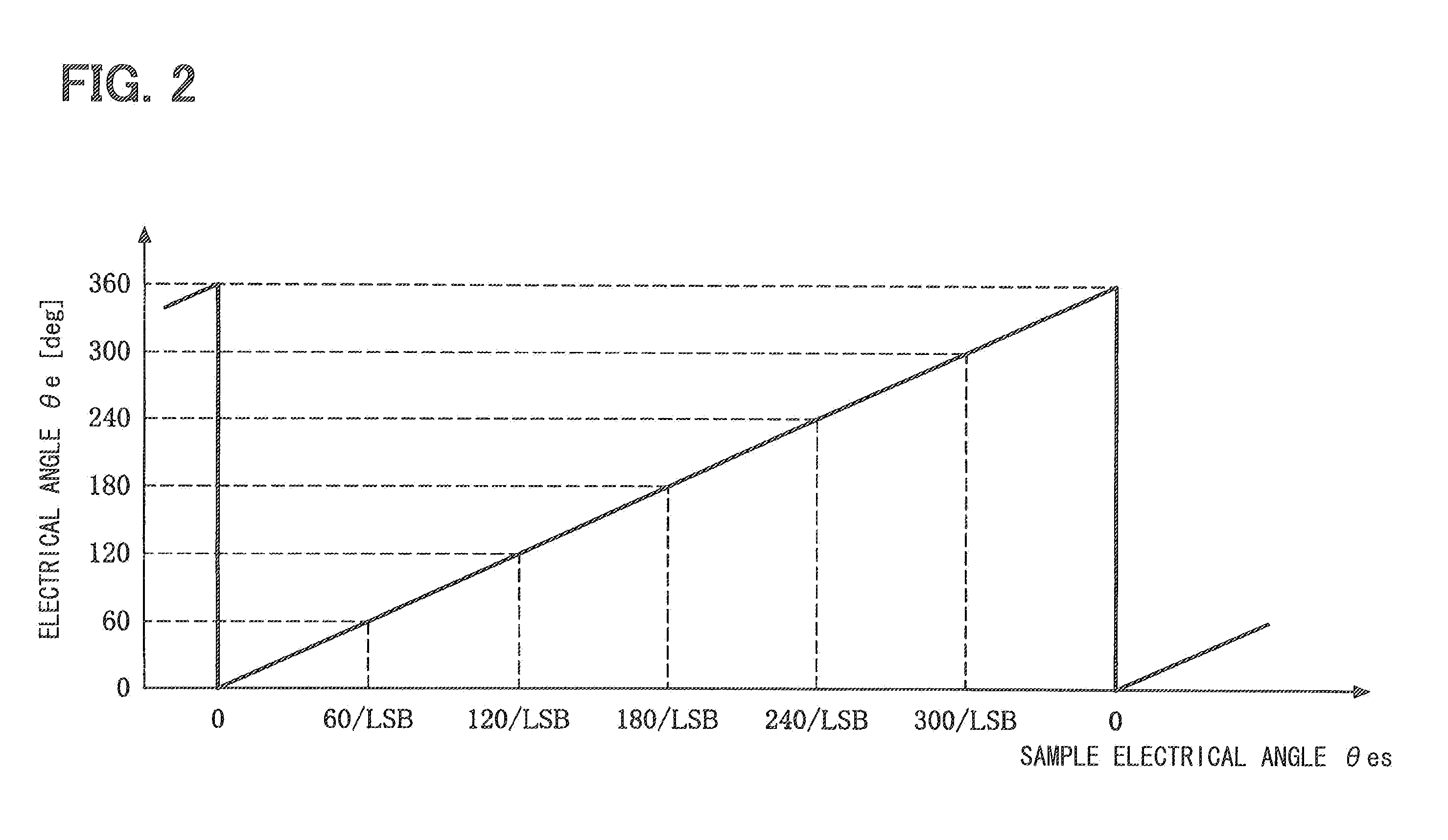
[0011]In view of the foregoing problems, it is an object of the present invention to provide an alternating current motor system that can perform a rectangular wave control with a high degree of accuracy based on a rotational position signal obtained by digitizing a detection signal of a rotational position sensor.
[0013]In the alternating current motor control system, the rotational position signal is obtained by digitizing the detection signal of the rotational position sensor with the resolution that the quotient when the electrical angle of 360 degrees is divided by the multiple of 3 is set to the quantization unit. Thus, the electrical angle of 60 degrees can be an integral multiple of the quantization unit. Therefore, the motor control portion can determine the electrical angle of 60 degrees with a high degree of accuracy without being influenced by an error of the rotational position signal and can perform the rectangular wave control with a high degree of accuracy.

Problems solved by technology

Thus, the control circuit is difficult to determine the electrical angle of 60 degrees by receiving an influence of an error due to the resolution of the rotational position signal, the control circuit is difficult to generate the rectangular wave voltages commutated every electrical angle of 60 degrees, and the control circuit is difficult to perform the rectangular wave control with a high degree of accuracy.

Method used


Image

  • Alternating current motor control system
  • Alternating current motor control system
  • Alternating current motor control system

Examples


Embodiment Construction

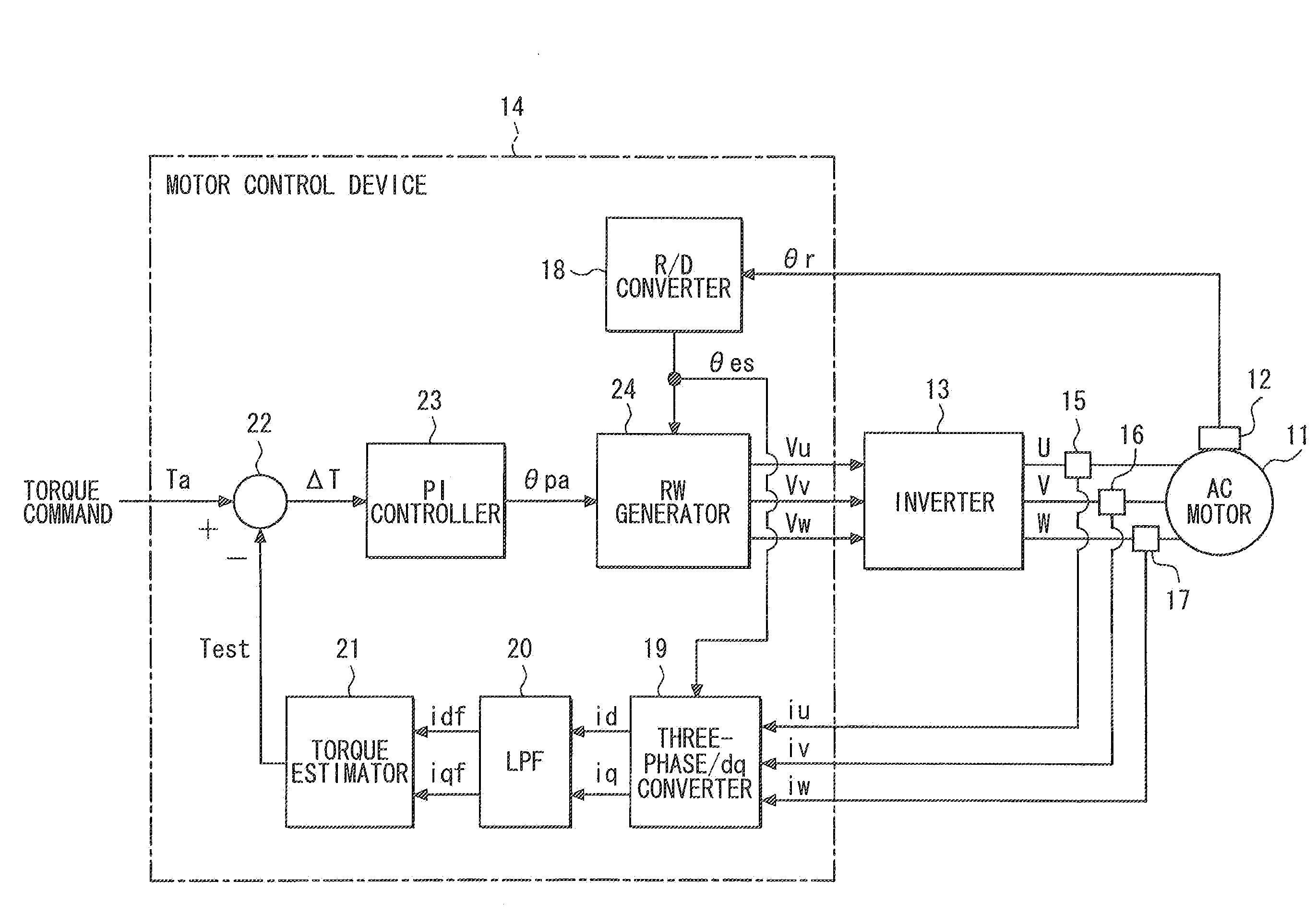
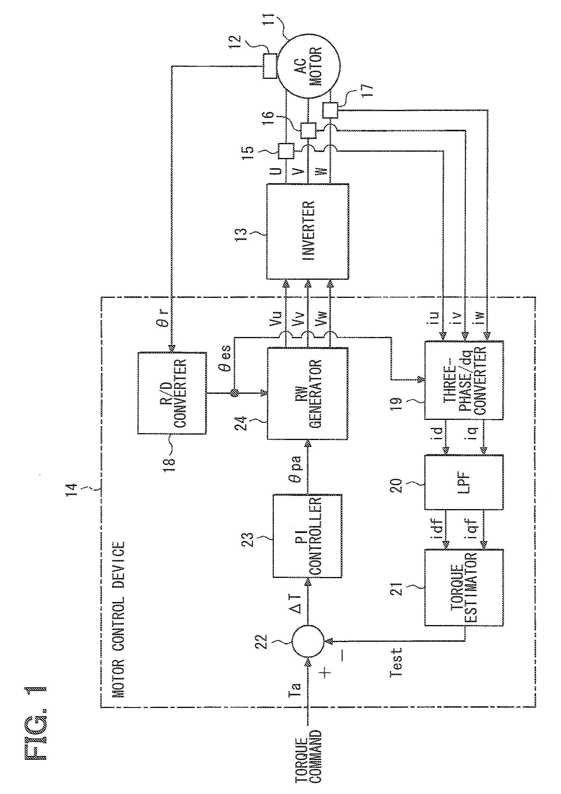
[0018]A motor control system according to an embodiment of the present invention will be described with reference to FIG. 1. The motor control system can be applied, for example, to an electric vehicle or a hybrid vehicle that uses an alternating current motor as a source of power. The motor control system includes an alternating current (AC) motor 11. The AC motor 11 is a three-phase permanent magnet synchronous motor used as a source of power of a vehicle. The AC motor 11 includes a permanent magnet. A rotational position sensor 12 for detecting a rotational position of a rotor is mounted to the AC motor 11. The AC motor 11 is driven by a voltage-controlled three-phase inverter 13. Based on three-phase voltage command signals “Vu,”“Vv,” and “Vm” output from a motor control device 14, the inverter 13 converts a direct current voltage supplied from a direct current power source (not shown) such as a secondary battery into three-phase alternating current voltages “U,”“V,” and “W” and...


PUM


Abstract

An alternating current motor control system includes a three-phase synchronous alternating current motor, a rotational position sensor, and a motor control portion. The three-phase synchronous alternating current motor includes a rotor. The rotational position sensor detects a rotational position of the rotor. The motor control portion digitizes a detection signal of the rotational position sensor into a rotational position signal with a resolution that a quotient when an electrical angle of 360 degrees is divided by a multiple of 3 is set to a quantization unit. The motor control portion performs a rectangular wave control of applying a rectangular wave voltage based on the rotational position signal so that an energizing current of the three-phase synchronous alternating current motor is commutated every electrical angle of 60 degrees.

Description

CROSS REFERENCE TO RELATED APPLICATIONS[0001]The present application is based on and claims priority to Japanese Patent Application No. 2009-210096 filed on Sep. 11, 2009, the contents of which are incorporated in their entirety herein by reference.BACKGROUND OF THE INVENTION[0002]1. Field of the Invention[0003]The present invention relates to an alternating current motor (AC motor) control system.[0004]2. Description of the Related Art[0005]On an electric vehicle and a hybrid vehicle, an AC motor is mounted as a driving source. A motor control system of the electric vehicle and the hybrid vehicle includes a three-phase synchronous AC motor and a rotational position sensor for detecting a rotational position of a rotor of the AC motor. The motor control system controls voltages applied to respective phases of the AC motor by controlling an inverter based on a detection signal of the rotational position sensor.[0006]As a technique for controlling an AC motor, JP-A-2006-311770 disclos...

Claims


Application Information

Patent Timeline
IPC IPC(8): H02P6/16H02P6/06H02P6/08H02P6/28H02P21/00H02P21/22H02P27/04
CPCG01R31/343H02P6/16H02P6/08
Inventor EGAMI, TSUNEYUKI
Owner DENSO CORP
Learn More