
Process and apparatus for electroplating substrates

a technology of electroplating substrates and electrochemical plating equipment, which is applied in the direction of electrolysis components, vacuum evaporation coatings, coatings, etc., can solve the problems of affecting the speed of the movement of objects, the length of the electrochemical plating apparatus for a given speed of movement must be very large, and the process produces no significant increase in throughput. , to achieve the effect of increasing the throughput of the substrate through the coating apparatus and the speed of the coating process

Inactive Publication Date: 2011-03-17
SCHOTT SOLAR AG (DE)
View PDF7 Cites 9 Cited by
  • Summary
  • Abstract
  • Description
  • Claims
  • Application Information

AI Technical Summary

Benefits of technology

[0010]It is an object of the present invention to increase the throughput of the substrate through the coating apparatus as well as the speed of the coating process.
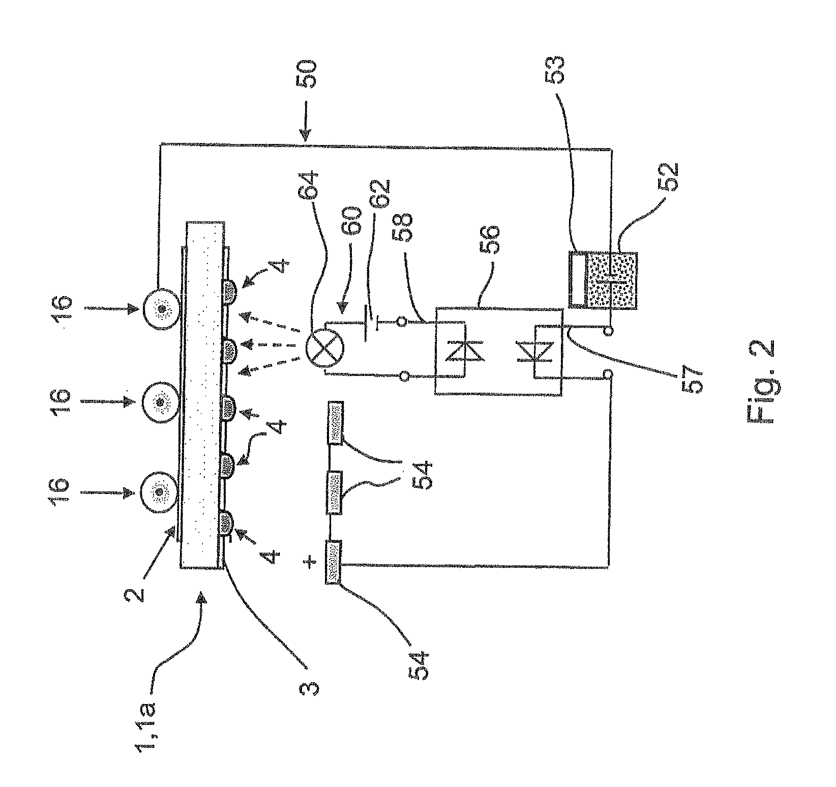
[0023]Preferably the light source circuit is coupled by means of an optocoupler with the electrolytic cell rectifier circuit. Because of the galvanic separation of the input and the output the coupling provided by the optocoupler has the advantage that interfering effects from one circuit will not be transmitted to the other circuit. The coupling of the circuits by means of an optocoupler thus provides the advantage of a greater stability and uniformity of the generated pulses.
[0028]It has been shown that the higher the flow speed of the coating liquid at the surface of the cathode area of the at least one substrate, the higher the limiting current density.

Problems solved by technology

However the combined light- and current-generated coating process produces no significant increase of throughput.
DE 42 25 961 A1 teaches that operating with constant direct voltage in an electroplating circuit is harmful.
That means that the length of the electrochemical plating apparatus for a given speed of movement of the object must be very great.

Method used


Image

  • Process and apparatus for electroplating substrates
  • Process and apparatus for electroplating substrates
  • Process and apparatus for electroplating substrates

Examples


Embodiment Construction

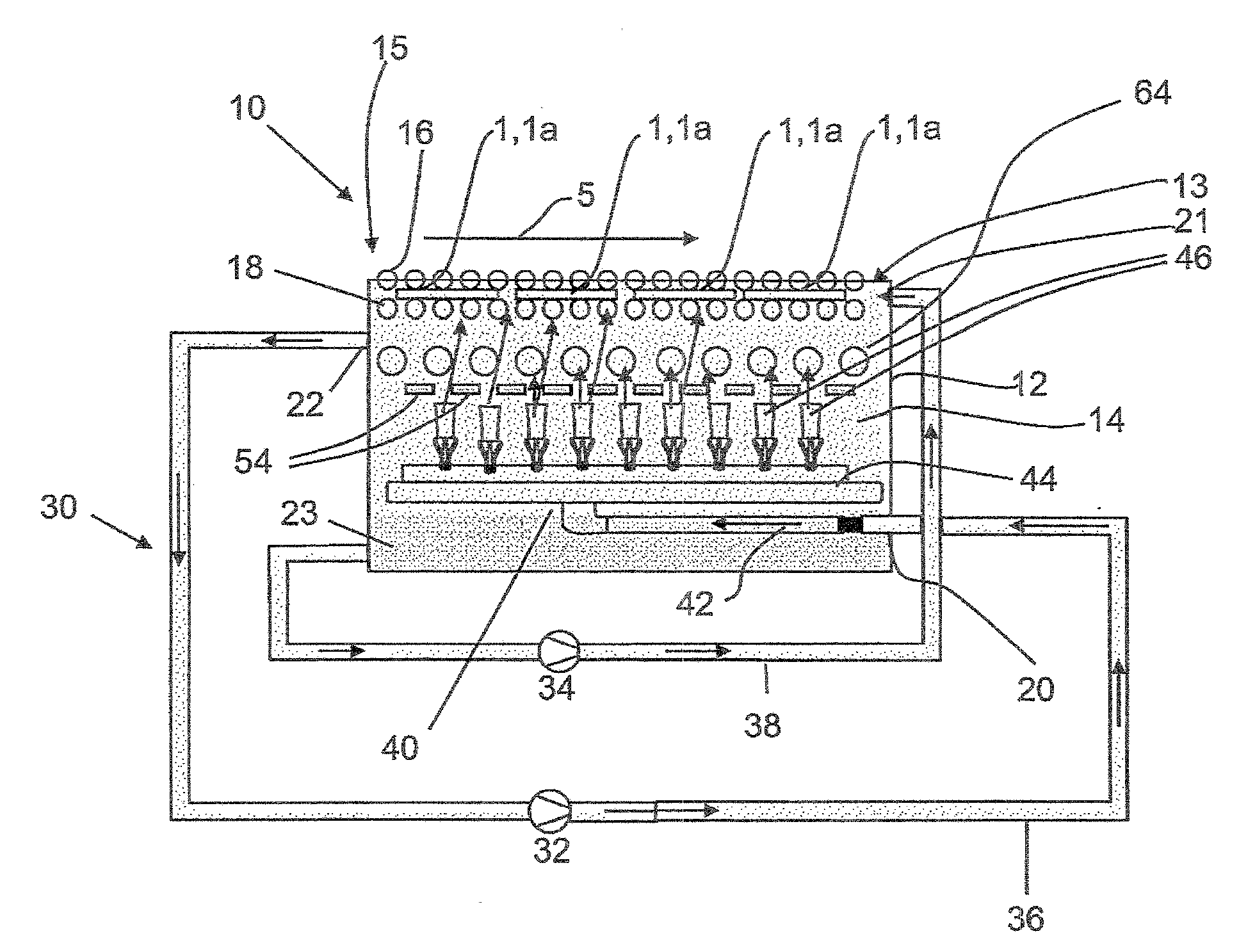
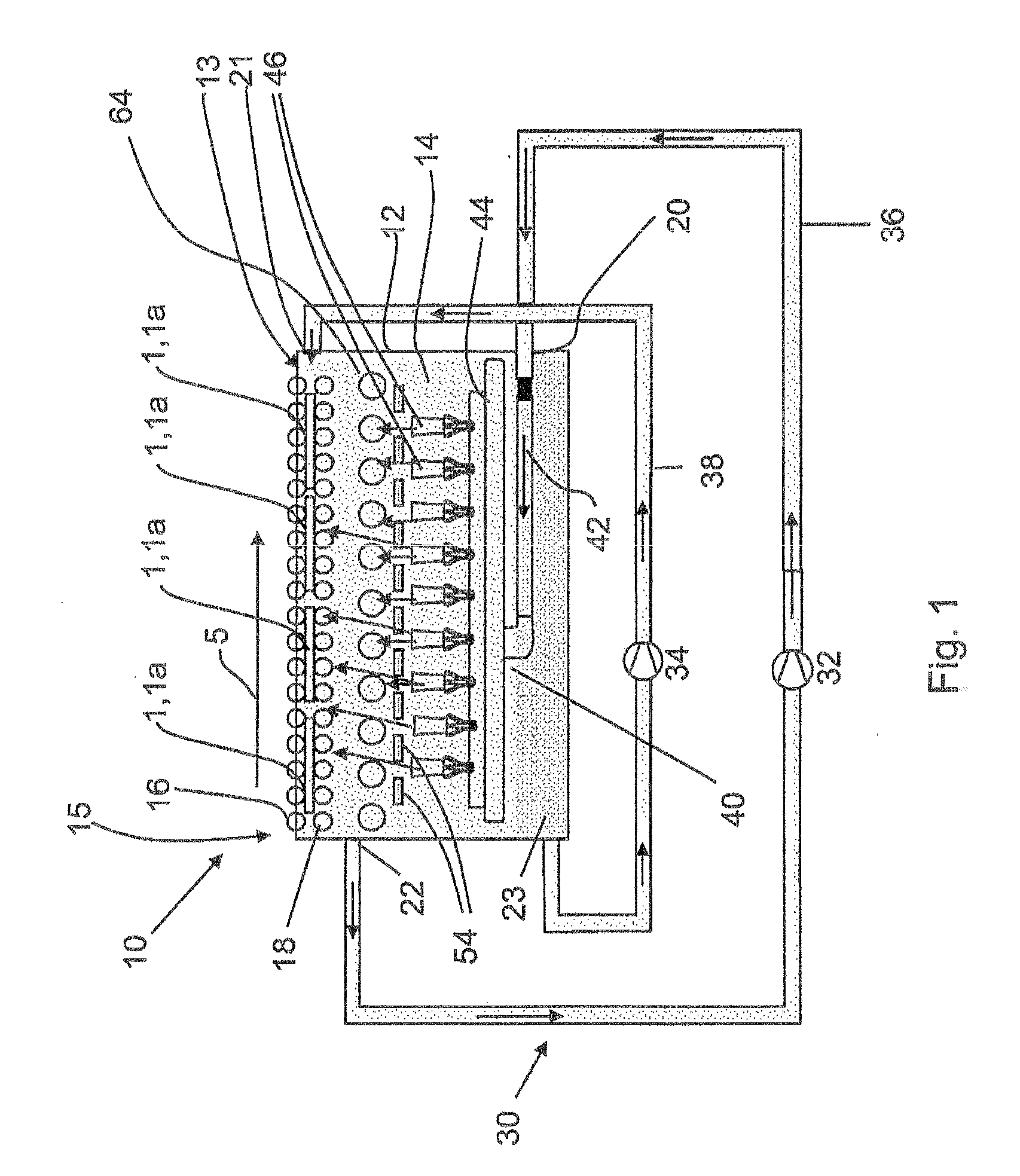
[0051]An apparatus 10 for coating substrates 1 is illustrated in FIG. 1. Solar cells 1a are used as substrates in the present example. The apparatus 10 includes a coating tank 12, which comprises a coating bath 13, which contains an electrolytic coating liquid 14.

[0052]A conveying device 15, which comprises upper conveying rollers 16 and lower conveying rollers 18, is provided in the upper part of the coating tank 12. The solar cells 1a are held between the upper and lower conveying rollers 16, 18 and conveyed in the direction of the arrow 5. Since the coating tank 12 is filled with the coating liquid 14, the solar cells 1a are completely within the coating bath 13.

[0053]A circulation device 30 for producing a flow in the coating bath 13, which has a first liquid conductor 36, is provided. The coating tank 12 has a first outlet 22 below the conveying device 15, to which the first liquid conductor 36 is connected. The coating liquid 14 is pumped from the coating tank 12 via the first...


PUM

PropertyMeasurementUnit
Timeaaaaaaaaaa
Timeaaaaaaaaaa
Timeaaaaaaaaaa

Abstract

An apparatus for electroplating one or more surfaces (2,3) on one or more substrates (1), especially solar cells (1a), is described. The apparatus includes an electrochemical coating bath (13), which has a coating tank (12) filled with an electrochemical coating liquid (14). The apparatus also includes a conveying device (15) for transporting the substrate through the coating bath (13), a light source circuit (60) with light sources (64) for irradiating the substrate (1) and an electrolytic cell rectifier circuit (50) for the substrate with anodes (54). The apparatus is characterized by a device for generating synchronous current pulses and light pulses, so that during a time interval between the current pulses the irradiating of the substrate or substrates is interrupted. A process for electrochemical plating of the surface of the substrate or substrates is also described.

Description

CROSS-REFERENCE[0001]The subject matter described and claimed herein below is also described in German Patent Application No. 10 2009 029 551.8, filed on Sep. 17, 2009 in Germany. This German Patent Application provides the basis for a claim of priority of invention for the invention described and claimed herein below under 35 U.S.C. 119 (a)-(d).BACKGROUND OF THE INVENTION[0002]1. The Field of the Invention[0003]The present invention relates to a process for electroplating at least one surface of at least one substrate, especially solar cells, in which the substrate is moved through an electrolyte coating liquid, is irradiated with light and an electroplating current is applied to the substrate by means of an electrolytic cell rectifier circuit.[0004]It also relates to an apparatus for performing the process, comprising an electrochemical coating bath, which comprises a coating tank filled with an electrochemical coating liquid, a conveying device for transporting the substrate thro...

Claims


Application Information

Patent Timeline
IPC IPC(8): C25D5/18C25B9/06C25B9/17
CPCC25D5/00C25D5/18H01L31/022425Y02E10/50C25D7/126C25D5/08C25D17/001C25D21/12C25D5/006C25D5/011
Inventor LIPPERT, LOTHARDAUWE, STEFAN
Owner SCHOTT SOLAR AG (DE)
Learn More