
Thin film type solar cell and method for manufacturing the same, and thin film type solar cell module and power generation system using the same

Inactive Publication Date: 2011-03-17
JUSUNG ENG
View PDF5 Cites 28 Cited by
  • Summary
  • Abstract
  • Description
  • Claims
  • Application Information

AI Technical Summary

Benefits of technology

[0022]An object of the present invention is to provide a thin film type solar cell with a plurality of unit cells connected in series, wherein uniform energy conversion efficiency is maintained in all of the unit cells by improving the energy conversion efficiency in the unit cell with the relatively-low energy conversion efficiency, to thereby realize the improved energy conversion efficiency.

Problems solved by technology

However, in the case of the wafer type solar cell, it is difficult to realize a small thickness due to difficulty in performance of the manufacturing process.
In addition, the wafer type solar cell uses a high-priced semiconductor substrate, whereby its manufacturing cost is increased.
With the increase in size of the substrate, energy conversion efficiency is deteriorated due to the increase in electrode resistance.
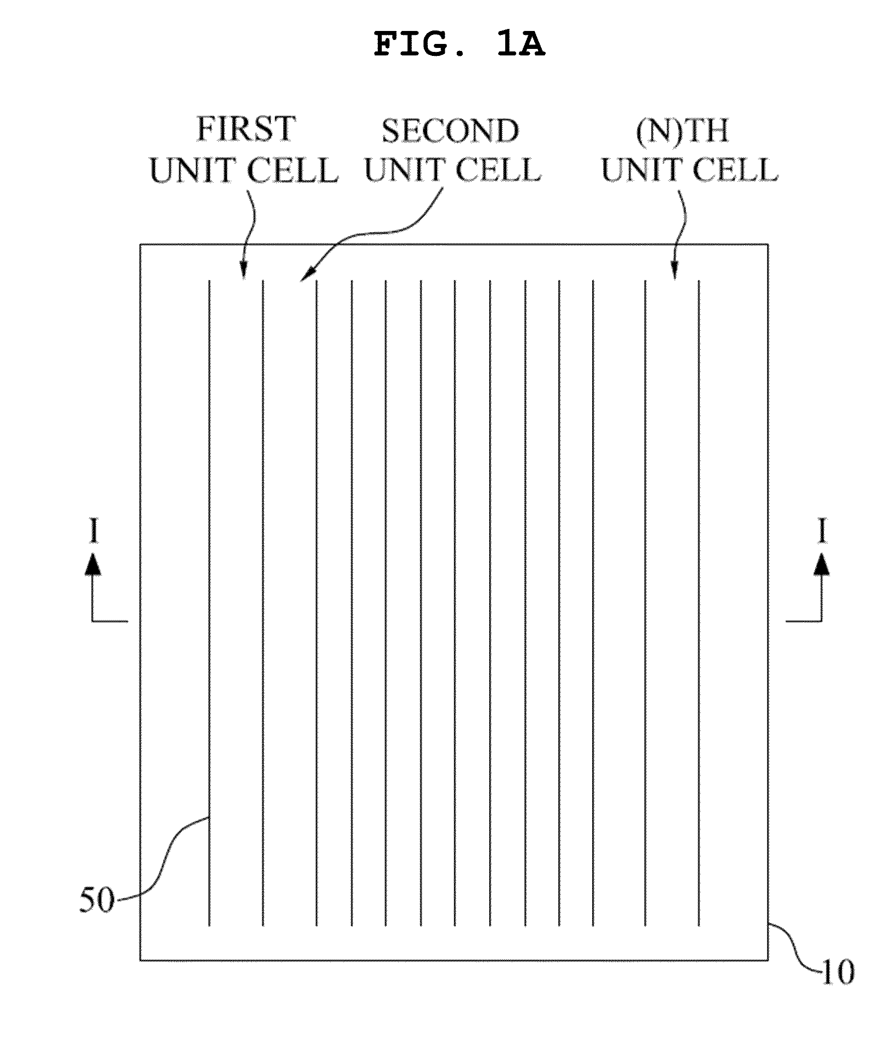
However, it is difficult to maintain uniformity in the energy conversion efficiency among the first to (n)th unit cells.
In case of the related art thin film type solar cell with the plurality of unit cells connected in series, the energy conversion efficiency is not uniform in all of the unit cells, that is, the energy conversion efficiency in some of the unit cells is relatively lower that that of the other unit cells, whereby the total energy conversion efficiency is deteriorated.

Method used


Image

  • Thin film type solar cell and method for manufacturing the same, and thin film type solar cell module and power generation system using the same
  • Thin film type solar cell and method for manufacturing the same, and thin film type solar cell module and power generation system using the same
  • Thin film type solar cell and method for manufacturing the same, and thin film type solar cell module and power generation system using the same

Examples


Embodiment Construction

[0041]Reference will now be made in detail to the preferred embodiments of the present invention, examples of which are illustrated in the accompanying drawings. Wherever possible, the same reference numbers will be used throughout the drawings to refer to the same or like parts.

[0042]Hereinafter, a thin film type solar cell according to the present invention will be described with reference to the accompanying drawings.

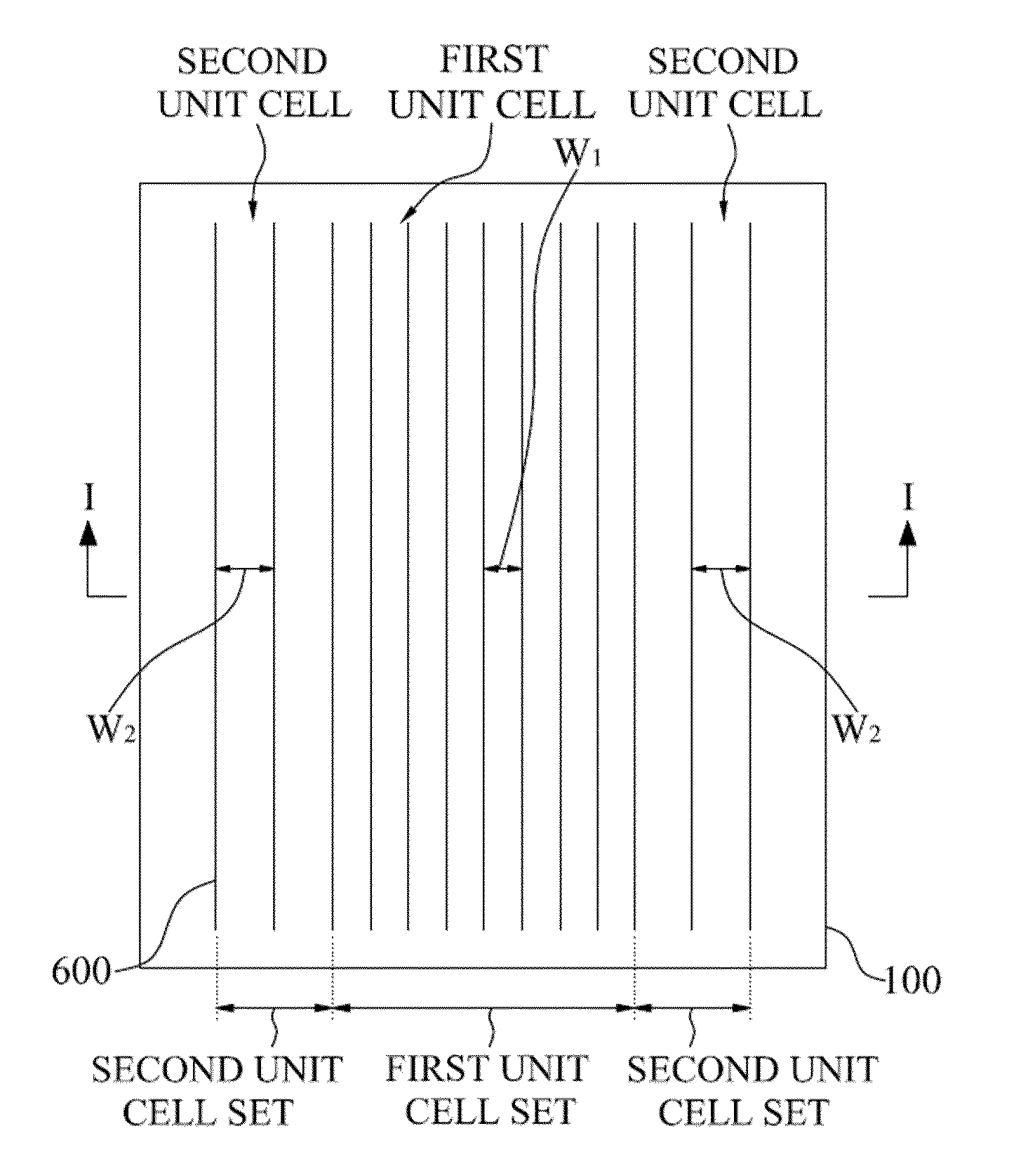
[0043]FIG. 3 is a plan view illustrating a thin film type solar cell according to one embodiment of the present invention.

[0044]As shown in FIG. 3, the thin film type solar cell according to one embodiment of the present invention includes a plurality of unit cells on a substrate 100. In more detail, the plurality of unit cells are connected in series, and are provided at fixed intervals by each separating channel 600 interposed in-between.

[0045]The plurality of unit cells constitute first and second unit cell sets, wherein the first unit cell set comprises first uni...


PUM


Abstract

A thin film type solar cell with a plurality of unit cells connected in series is disclosed, wherein uniform energy conversion efficiency is maintained in all of the unit cells by improving the energy conversion efficiency in the unit cell with the relatively-low energy conversion efficiency, to thereby realize the improved energy conversion efficiency, the thin film type solar cell comprising the plurality of unit cells, each unit cell including a front electrode, a semiconductor layer, and a rear electrode sequentially deposited on a substrate, wherein the thin film type solar cell includes a first unit cell set including at least one first unit cell with a first cell width, and a second unit cell set including at least one second unit cell with a second cell width which is different from the first cell width, wherein the first unit cell set occupies 80 to 95% of an entire area of the unit cells, and the second unit cell set occupies 5 to 20% of the entire area of the unit cells.

Description

CROSS REFERENCE TO RELATED APPLICATIONS[0001]This application claims the benefit of the Korean Patent Application No. P2009-0087329, filed on Sep. 16, 2009, which is hereby incorporated by reference as if fully set forth herein.BACKGROUND OF THE INVENTION[0002]1. Field of the Invention[0003]The present invention relates to a thin film type solar cell, and more particularly, to a thin film type solar cell with a plurality of unit cells connected in series.[0004]2. Discussion of the Related Art[0005]A solar cell with a property of semiconductor converts a light energy into an electric energy.[0006]A structure and principle of the solar cell according to the related art will be briefly explained as follows. The solar cell is formed in a PN-junction structure where a positive (P)-type semiconductor makes a junction with a negative (N)-type semiconductor. When solar ray is incident on the solar cell with the PN-junction structure, holes (+) and electrons (−) are generated in the semicond...

Claims


Application Information

Patent Timeline
IPC IPC(8): H01L31/042H01L31/00
CPCH01L31/022433H01L31/03921H01L31/075H01L31/0463Y02E10/548H01L31/035272H01L31/046H01L31/076H01L31/0445
Inventor PARK, CHANG KYUNKANG, HYUNG DONG
Owner JUSUNG ENG
Learn More