Image forming apparatus and image forming method

Inactive Publication Date: 2011-03-10
SEIKO EPSON CORP
View PDF3 Cites 8 Cited by
  • Summary
  • Abstract
  • Description
  • Claims
  • Application Information

AI Technical Summary

Benefits of technology

[0009]An advantage of some aspects of the invention is to provide a technique that solves the aforementioned problems arising when forming an image onto recording paper by causing the recording paper to pass through a transfer nip formed by a transfer roller having a concaved portion in one part of its circumferential surface making contact with an image bearing belt, and is thus capable of forming an image onto recording papers of various types in a favorable manner.
[0012]In the aspects of the invention (the image forming apparatus and the image forming method) configured in this manner, a transfer nip is formed by the circumferential surface of the transfer roller making contact with the image bearing belt, and the image formed on the image bearing belt is transferred onto the recording paper by the recording paper passing through the transfer nip. Because the recording paper follows the rotational frequency of the transfer roller when the recording paper passes through the transfer nip, it is possible to control the speed of movement of the recording paper in accordance with the rotational frequency of the transfer roller. Accordingly, in the invention, the rotational frequency of the transfer roller is controlled based on information of the paper type of the recording material when the recording paper is nipped in the transfer nip, thus suppreg a speed difference between the speed of movement of the recording paper and the speed of movement of the transfer belt. As a result, abrasions can be suppressed from occurring in the image at the transfer nip, and speed fluctuations in the image bearing belt can be suppressed, thus making it possible to form a favorable image upon the recording paper.

Problems solved by technology

On the other hand, there is a risk that the recording material will stick to the image bearing member if a high amount of pressure is applied in such a manner.
This is actually because a difference in the speeds of movement causes the occurrence of abrasions in the image.
This is also because the burden on the driving source of the transfer belt is increased due to a difference in the speeds of movement as described above; this leads to disturbances in the speed of movement of the transfer belt, which in turn makes it impossible to carry out the primary transfer of the image onto the transfer belt in a favorable manner.
However, there are various types of recording material, and there are cases where the speed of movement of the transfer belt and the speed of movement of the recording material are skewed from each other depending on the type of the recording material that passes through the transfer nip.
The amount of skew between the speeds of movement is particularly severe in the case where the thicknesses of recording materials differ.
Accordingly, with the aforementioned apparatus, it has been difficult to form an image in a favorable image quality onto recording papers of various types, and the apparatus has thus been problematic in terms of its general applicability.

Method used


Image

  • Image forming apparatus and image forming method
  • Image forming apparatus and image forming method
  • Image forming apparatus and image forming method

Examples


Embodiment Construction

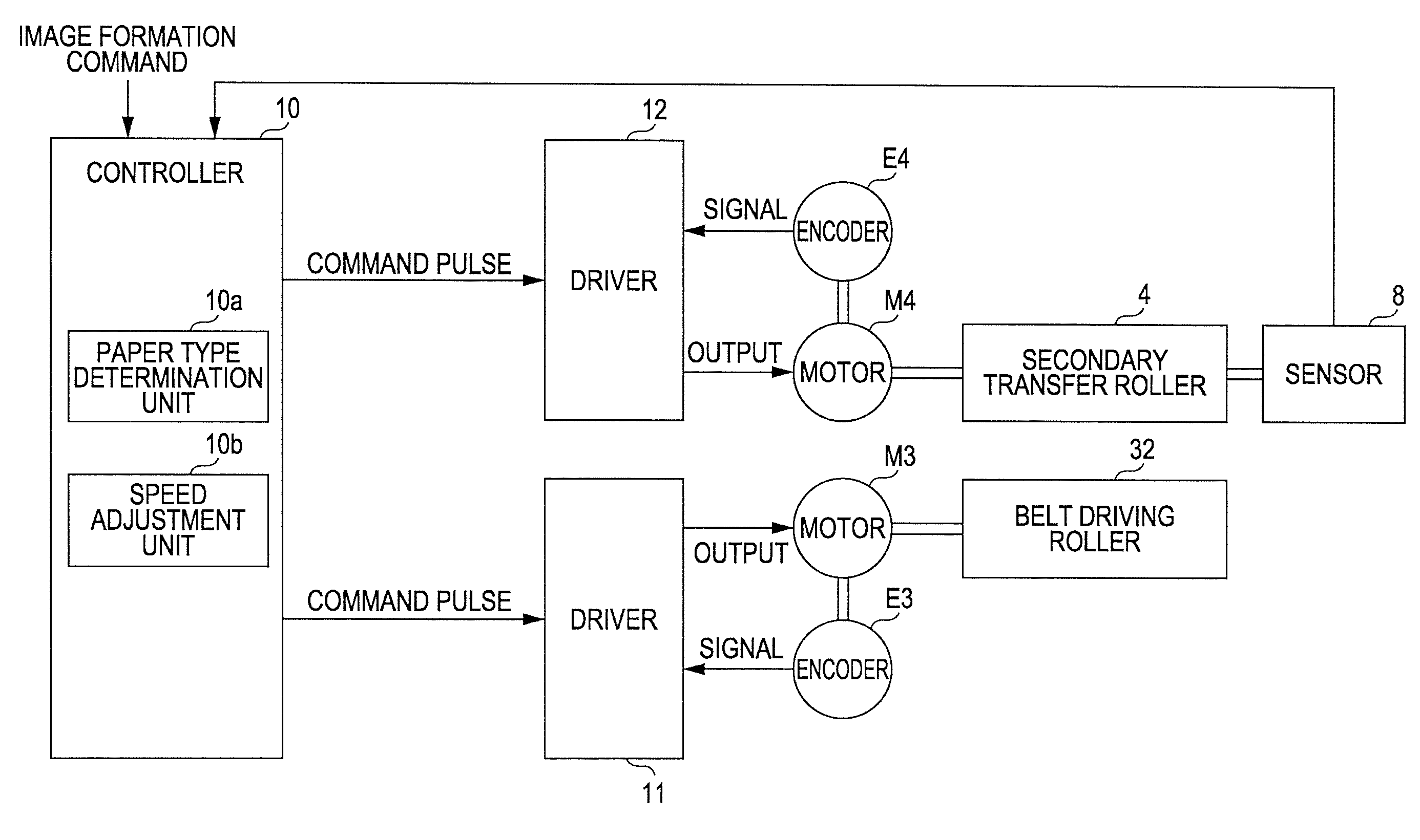
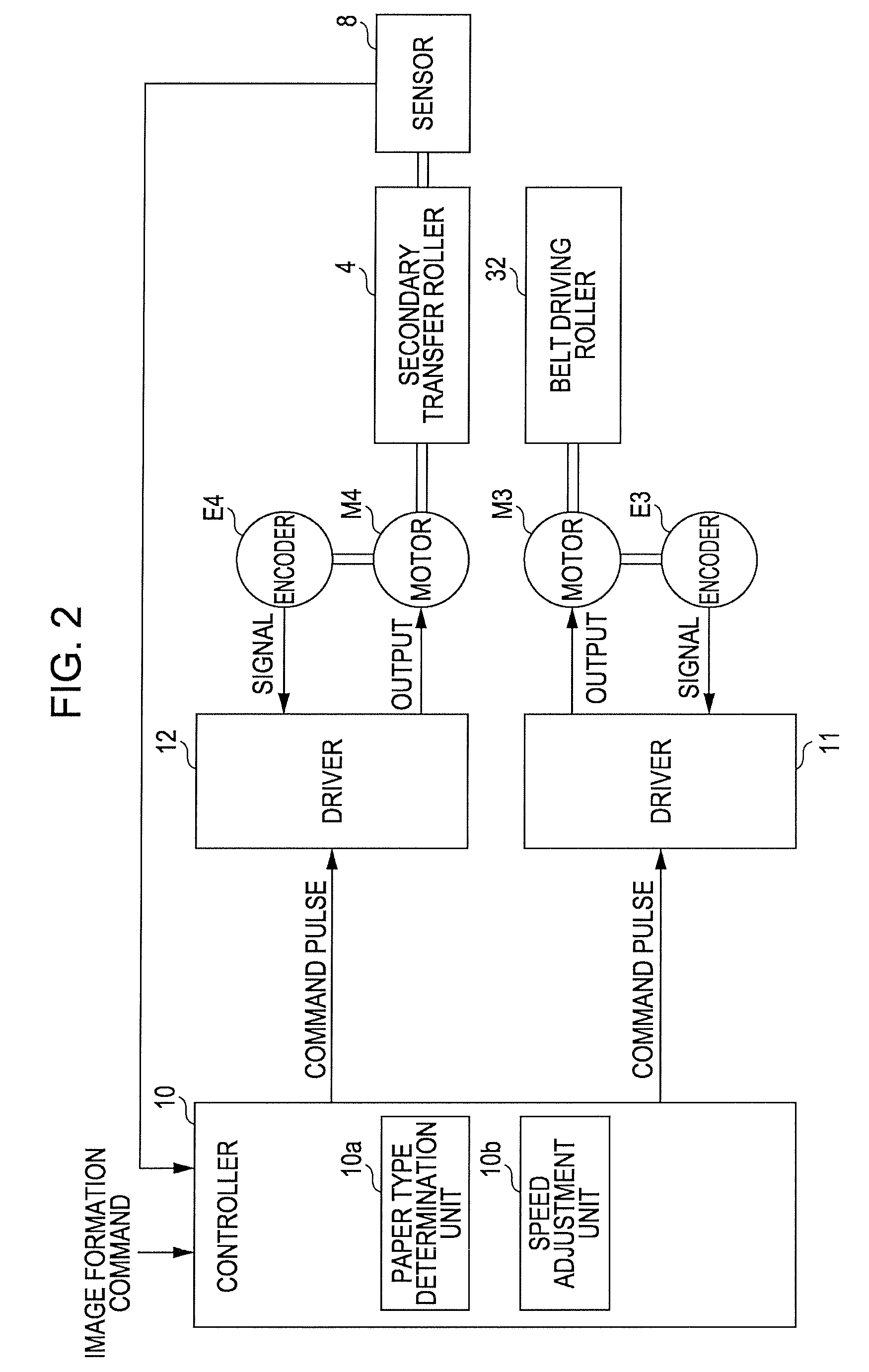
[0023]FIG. 1 is a diagram illustrating an embodiment of an image forming apparatus according to the invention. FIG. 2, meanwhile, is a block diagram illustrating an electrical configuration of the apparatus illustrated in FIG. 1. This image forming apparatus 1 includes four image forming stations, or 2Y (for yellow), 2M (for magenta), 2C (for cyan), and 2K (for black), that form images of their respective colors, serving as “image creation units” according to the invention. The image forming apparatus 1 is capable of selectively executing a color mode, in which a color image is formed by superimposing yellow (Y), magenta (M), cyan (C), and black (K) toners upon each other, and a monochromatic mode, in which a monochromatic image is formed using only black (K) toner. With this image forming apparatus, when an external device such as a host computer or the like provides a controller 10 including a CPU, a memory, and the like with an image formation command, the controller 10 executes ...


PUM


Abstract

An image forming apparatus including: an image bearing belt that bears an image; an image creation unit that transfers the image on the image bearing belt; a first driving source; a driving roller that is rotationally driven by the first driving source and causes the image bearing belt to move; a transfer roller that has a concaved portion in a circumferential surface, forms a transfer nip by the transfer roller making contact with the image bearing belt, and transfers the image on the image bearing belt to a recording material; a second driving source that rotationally drives the transfer roller; a material type determination unit that determines a type of the recording material; and a control unit that controls a number of rotation of the transfer roller when the recording material is nipped by the transfer nip based on information of the type determined by the material type determination unit.

Description

BACKGROUND[0001]1. Technical Field[0002]The present invention relates to an image forming apparatus that includes an image bearing belt that bears an image and a transfer roller that forms a transfer nip by making contact with the image bearing belt and that has a concaved portion in one part of its circumferential surface, and an image forming method for such an image forming apparatus.[0003]2. Related Art[0004]There are, in the field of image forming techniques for forming images upon recording material such as paper, apparatuses configured to transfer an image that has first been formed on an image bearing belt onto the recording material. For example, with an image forming apparatus disclosed in JP-A-2008-122815 (see FIG. 1 of JP-A-2008-122815), an image forming station forms an image upon a transfer belt, serving as an image bearing member, that is stretched upon multiple rollers, and the image is transferred from the transfer belt onto recording material by causing the recordi...

Claims


Application Information

Patent Timeline
IPC IPC(8): G03G15/00G03G15/16G03G15/01
CPCG03G15/167G03G2215/0196G03G2215/00751G03G15/5029
Inventor SAKA, YOSHIHISANOMURA, YUJIRO
Owner SEIKO EPSON CORP
Why Eureka
Try Eureka