
Series solar system with current-matching function

a solar system and solar panel technology, applied in the field of solar systems, can solve the problems of solar panel damage and reduce the energy conversion efficiency of the series solar system

Inactive Publication Date: 2011-03-10
INERGY TECH
View PDF4 Cites 141 Cited by
  • Summary
  • Abstract
  • Description
  • Claims
  • Application Information

AI Technical Summary

Benefits of technology

[0007]The objective of the present invention is to provide

Problems solved by technology

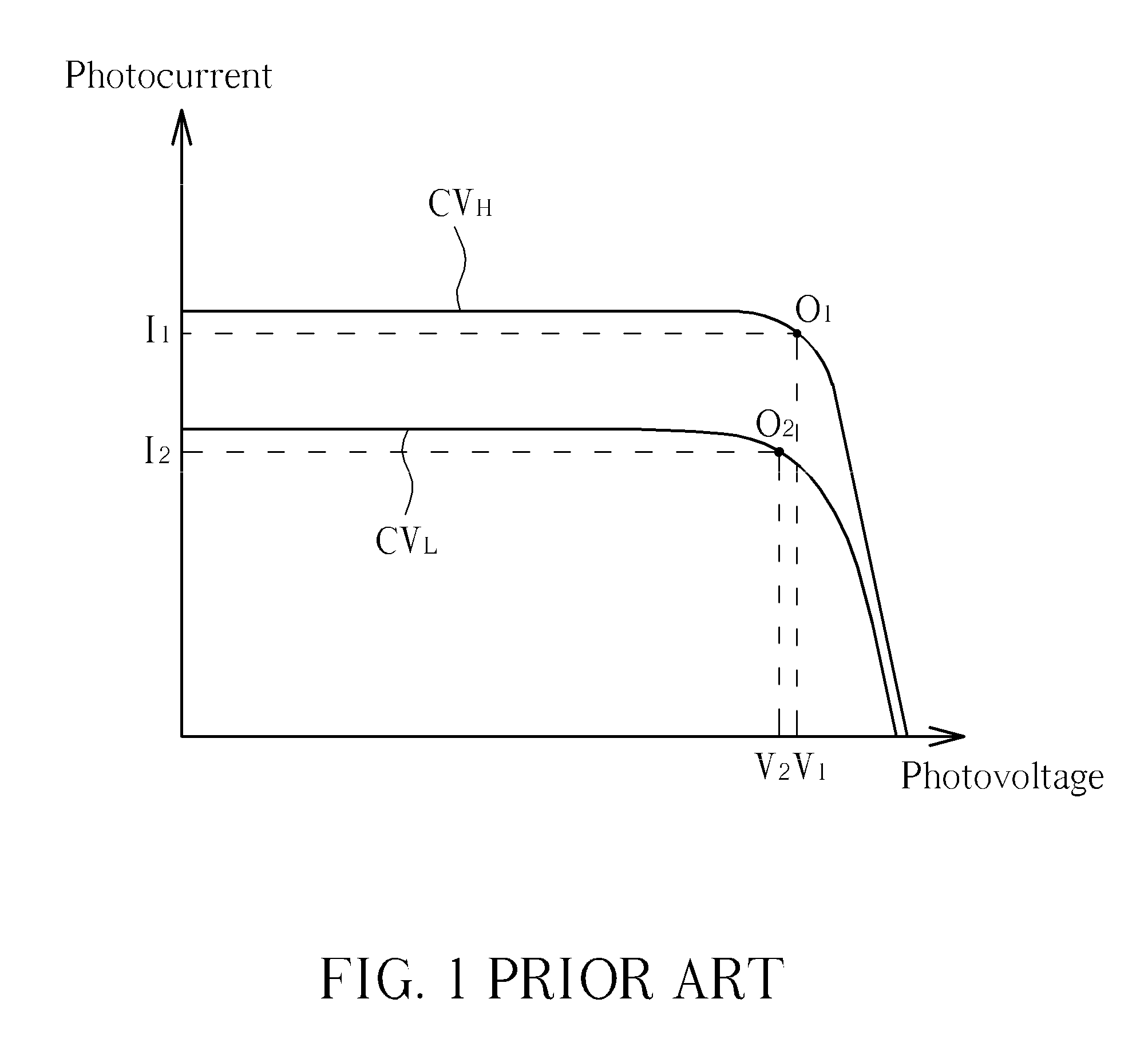
If the external circuit is to drain a current with a magnitude larger than I2 (for example, I1) from the solar panel, the solar panel may be damaged.
Therefore, in the series system, when one of the solar panels is covered, all the other uncovered solar panel are affected and can not generate the maximum output power, reducing the energy conversion efficiency of the series solar system.

Method used


Image

  • Series solar system with current-matching function
  • Series solar system with current-matching function
  • Series solar system with current-matching function

Examples


first embodiment

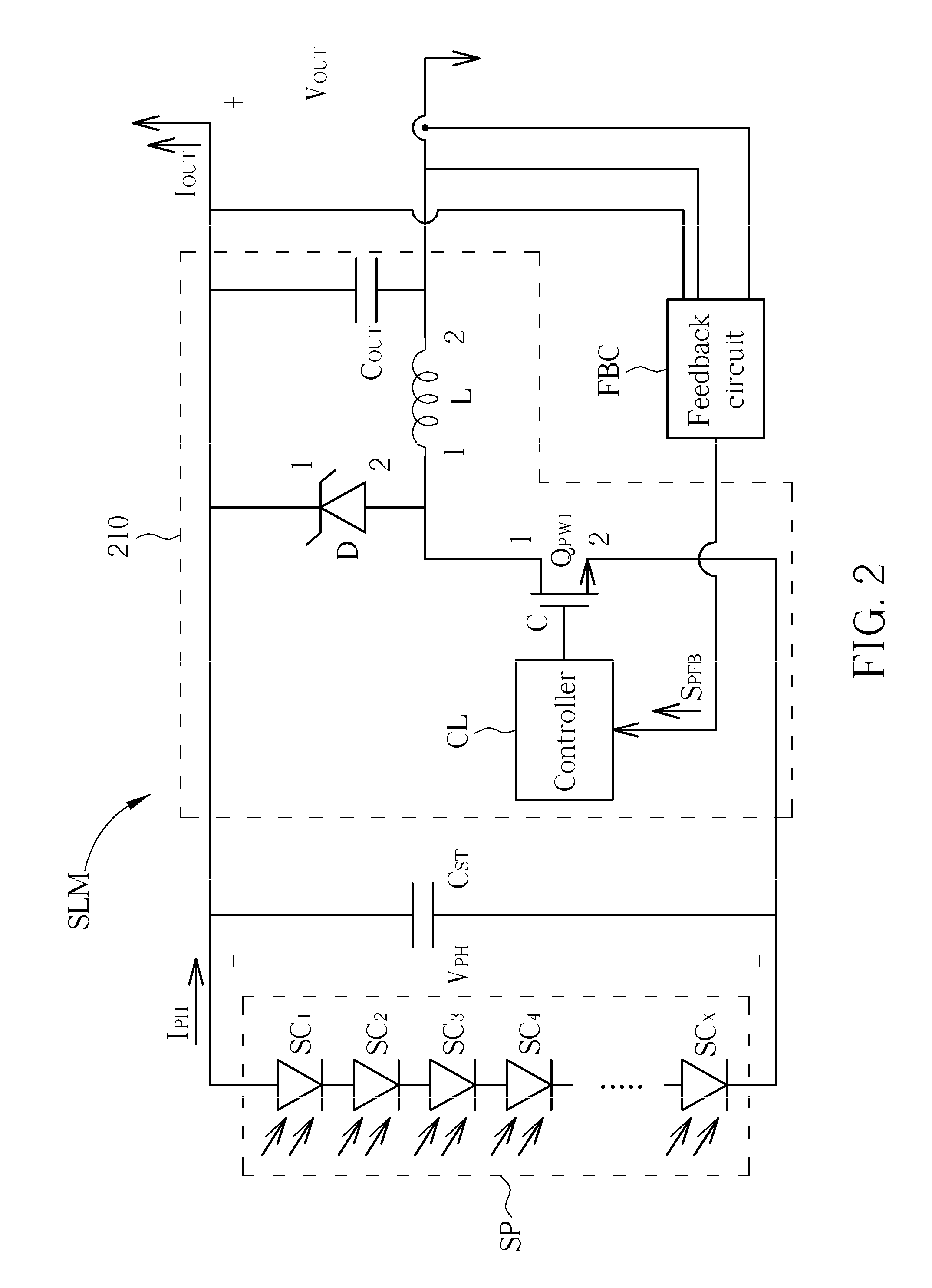
[0019]Please refer to FIG. 3A. FIG. 3A is a schematic diagram illustrating the method that the controller CL adjusts the duty cycle of the power switch QPW1 according to the power-feedback signal SPFB, according to the present invention. The periods of the solar module SLM operating can be divided into the first detecting periods T11˜T1K and the second detecting periods T21˜T2K, wherein the period lengths of the first detecting periods T11˜T1K and the second detecting periods T21˜T2K are all equal to one cycle T. During the first detecting period T11, the controller CL controls the power switch QPW1 operating with the first duty cycle DUTY11. That is, the DC / DC converter 210 operates with the first duty cycle DUTY11 at the time. During the second detecting period T21, the controller CL controls the power switch QPW1 operating with the second duty cycle DUTY21. That is, the DC / DC converter 210 operates with the second duty cycle DUTY21 at the time. Assume that the second duty cycle D...

second embodiment

[0020]Please refer to FIG. 3B. FIG. 3B is a schematic diagram illustrating the method that the controller CL adjusts the duty cycle of the power switch QPW1 according to the power-feedback signal SPFB, according to the present invention. The periods of the solar module SLM operating can be divided into the detecting periods T31˜T3K, wherein the period lengths of the detecting periods T31˜T3K are all equal to one cycle T. In FIG. 3B, the controller CL controls the power switch QPW1 operating with the duty cycle DUTY31 during the detecting period T31; the controller CL controls the power switch QPW1 operating with the duty cycle DUTY32 during the detecting period T32, wherein the duty cycle DUTY32 is smaller than the duty cycle DUTY31. If the received power-feedback signal SPFB32 of the controller CL corresponding to the detecting period T32 is larger than the received power-feedback signal SPFB31 of the controller CL corresponding to the detecting period T31, it represents that the c...


PUM


Abstract

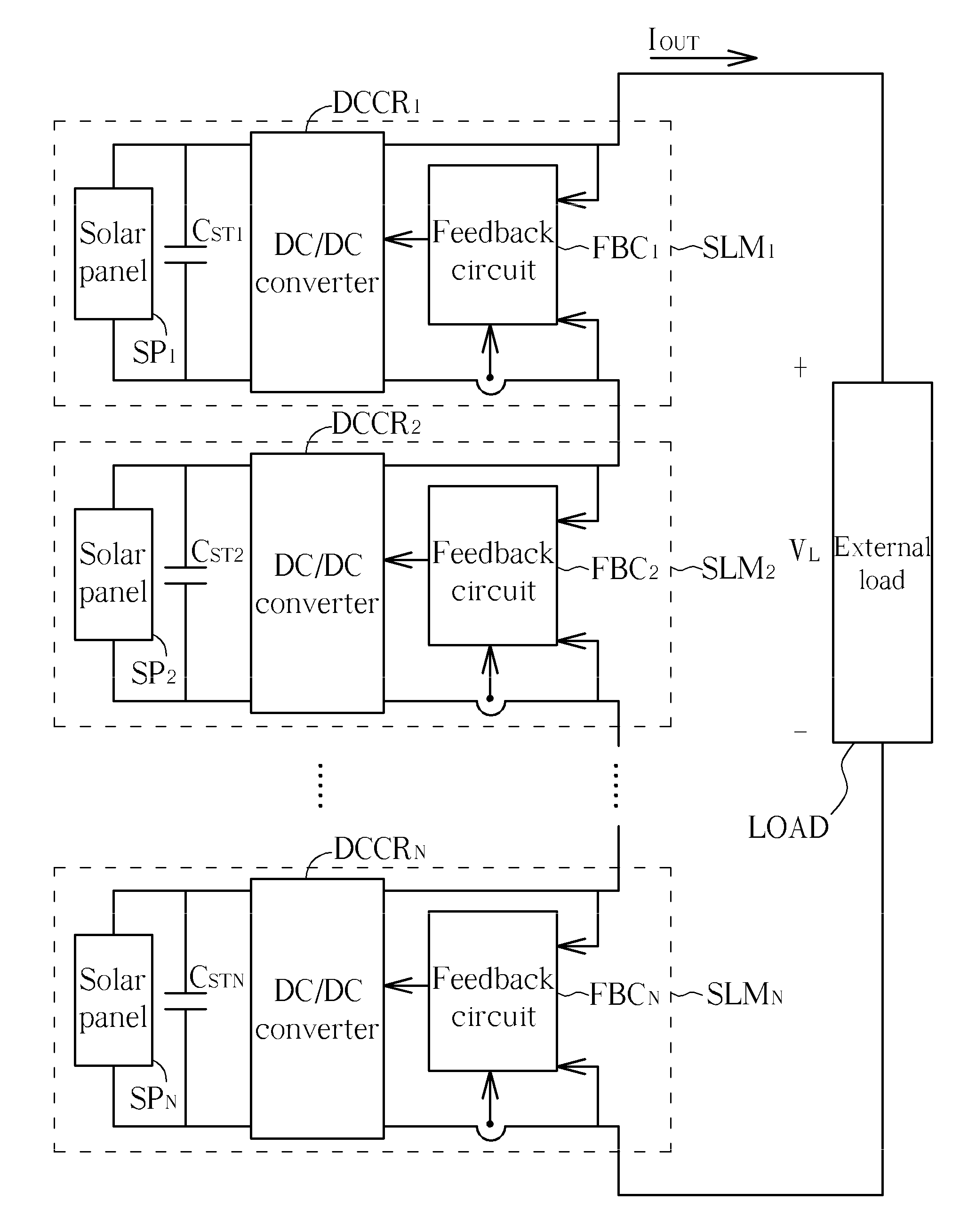
A series solar system with current-matching function includes a plurality of solar modules. The plurality of the solar modules is electrically connected in series. Each solar module includes a DC / DC converter and a solar panel electrically connected in parallel. The photocurrent generated by the solar panel is matched with the current generated by the solar panel operating at the optimum operating point by means of adjusting the duty cycle of the DC / DC converter, so that the solar panel can generate maximum output power. Therefore, in the series solar system, even a solar module is covered, causing the received light intensity of the solar module is reduced, and the series solar system still can generate maximum output power.

Description

BACKGROUND OF THE INVENTION[0001]1. Field of the Invention[0002]The present invention is related to a solar system, and more particularly, to a solar system with current-matching function.[0003]2. Description of the Prior Art[0004]The solar panels are utilized for forming a solar system (power system) so as to convert the solar energy into electrical power. The solar panel can receive light beams and accordingly generates a photocurrent and a photovoltage. The solar system can be grid-connected for providing an output current and a load voltage. The solar system formed by the solar panels can be a series solar system (the solar panels are electrically connected in series), or a parallel solar system (the solar panels are electrically connected in parallel). Comparing with the parallel solar system, the series solar system can generate the higher load voltage and the smaller output current. Since the conduction loss can be reduced when the magnitude of the output current of the solar...

Claims


Application Information

Patent Timeline
IPC IPC(8): H01L31/042H02J1/00
CPCH01L31/02021H02J3/383H02M3/158Y02E10/58H02J3/385Y02E10/563H02M2001/0077H02J2300/26H02J2300/24H02J3/381Y02E10/56H02M1/0077
Inventor KUAN, KAN-SHENG
Owner INERGY TECH
Learn More