
Landing gear uplock mechanism employing thermal phase-change actuation

a technology of thermal phase-change actuation and uplock mechanism, which is applied in the direction of steam engine plants, machines/engines, hot gas positive displacement engine plants, etc., can solve the problems of complex hydraulic actuation system, unreliable, and unnecessary weight for aircraft to carry,

Active Publication Date: 2011-03-10
SAFRAN LANDING SYST CANADA INC
View PDF13 Cites 14 Cited by
  • Summary
  • Abstract
  • Description
  • Claims
  • Application Information

AI Technical Summary

Problems solved by technology

Disadvantageously, hydraulic actuation system are complex and add unnecessary additional weight for the aircraft to carry.
However, electrical actuation systems are complex to manufacture and not fully reliable.
In the case of a failure in which the landing gear lifting mechanism becomes inoperable, the weight of the gear on the hook would be too much for the solenoid to release.
Electromechanical actuators have a high level of complexity and a number of vexing failure modes.

Method used


Image

  • Landing gear uplock mechanism employing thermal phase-change actuation
  • Landing gear uplock mechanism employing thermal phase-change actuation
  • Landing gear uplock mechanism employing thermal phase-change actuation

Examples


Embodiment Construction

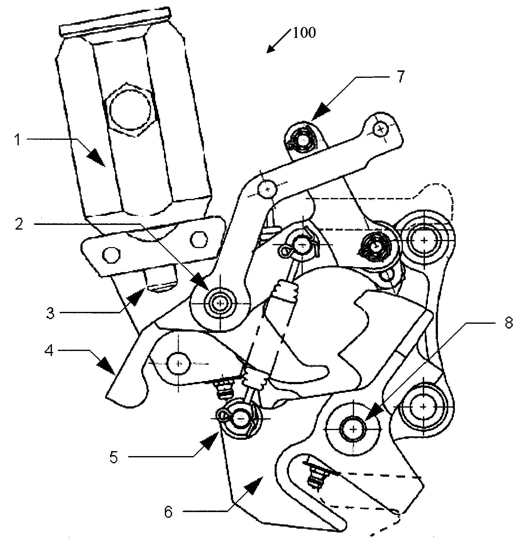
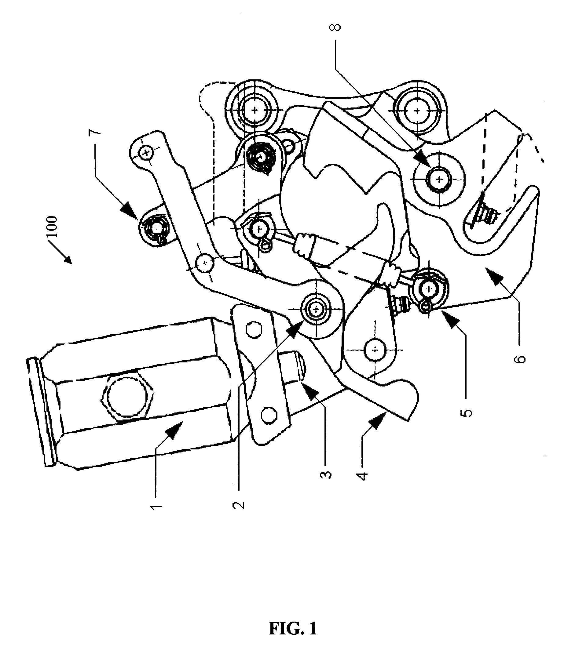
[0021]According to an embodiment illustrated in FIG. 1, there is provided an uplock assembly 100 comprising a thermal actuator 1 for actuating an uplock release mechanism 4 and releasing a catch hook 6 to release landing gears and / or doors of an aircraft which are in the closed and retracted position. For example, this may occur to free the gear for landing of the aircraft. As will be understood by a person skilled in the art, thermal actuators may also be referred to as paraffin actuators or wax actuators.

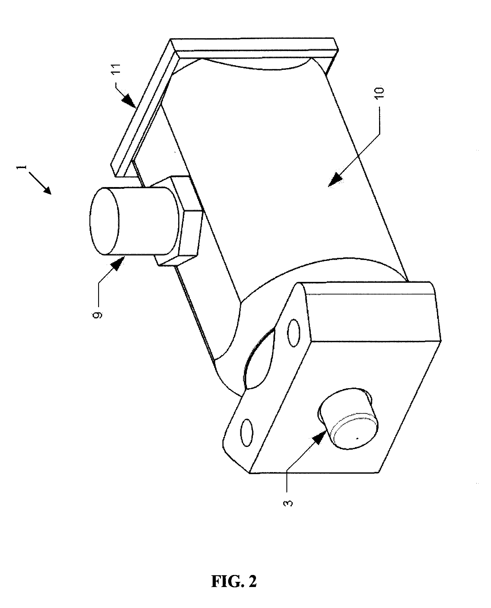
[0022]As will be described, the thermal actuator 1 further comprises a substantially enclosed chamber (e.g. cylindrical) configured to contain expansible material 15 (e.g. paraffin wax, FIG. 3) that undergoes volumetric change due to a temperature change (such as paraffin wax, or other waxes or materials that are able to expand in volume during a solid to liquid phase change caused by heating of the material). Preferably, the cylindrical chamber is rigid. The thermal actuator 1 fu...


PUM


Abstract

An uplock assembly for retaining and releasing landing gear systems, said uplock assembly comprising: a thermal actuator comprising: a chamber configured to contain expansible material therein; a heating mechanism coupled to said chamber for heating said expansible material and causing volumetric expansion thereof; a piston slidably coupled to said chamber and adapted to extend in response to said volumetric expansion; and an uplock release mechanism releasably engaged by said piston when extended such that said engaged uplock release mechanism causes the release of said landing gear.

Description

FIELD OF THE INVENTION[0001]The present invention relates to landing gear control systems and in particular mechanisms for the retention and release of the landing gear when in the retracted position.BACKGROUND OF THE INVENTION[0002]Aircraft uplock mechanisms are designed to lock the landing gear in a retracted position and assist in carrying the weight of the gear during flight. Conventional uplock mechanisms consist of a spring-loaded catch that locks the gear in place and a hydraulic cylinder to release the locking mechanism to free the gear to be lowered for landing.[0003]Current aircraft systems typically use a multitude of hydraulic subsystems as a source of mechanical energy. Typical state of the art uplocks employ one hydraulic actuator to perform the unlocking function, and often use a manually actuated cable system to perform the unlocking in the case of a hydraulic system failure. Other existing uplocks employ a secondary hydraulic actuator for the alternate release. Disa...

Claims


Application Information

Patent Timeline
IPC IPC(8): B64C25/26F15B5/00F03G7/06
CPCF03G7/06B64C25/26
Inventor SCHMIDT, R. KYLESINCLAIR, MICHAELCHAN, EDWARD CHUN KEI
Owner SAFRAN LANDING SYST CANADA INC
Learn More