
Method for manufacturing artificial implants

a technology of artificial implants and manufacturing methods, applied in image enhancement, programme control, instruments, etc., can solve the problems of inability to achieve effective matching of the cranium, variable appearance and unfamiliarity of patients, and inability to provide effective reconstruction

Active Publication Date: 2011-03-03
INSIGHTX TECH CORP
View PDF4 Cites 8 Cited by
  • Summary
  • Abstract
  • Description
  • Claims
  • Application Information

AI Technical Summary

Benefits of technology

[0012]As described in the previous texts, the method for manufacturing artificial implants according to the present invention may provide the following advantages:
[0014](2) the profile of the artificial implant created in accordance with the method of the present invention highly resembles the incised part, such that desirable match between the artificial implant and the surgical incisions can be successfully achieved;

Problems solved by technology

(1) the cranium may not be perfectly symmetric in horizontal orientation, thus the aforementioned minoring reconstruction approach is probably not able to completely restore the original head shape before surgery, causing variation and unfamiliarity in patient's appearance;
(2) by using the mirroring method, it is incapable of resulting in effective match between the cranium and operation incisions, even through manual adjustment may be performed by professional technicians;
(3) due to limits implicitly caused by mirroring samplings, the aforementioned method can be only applicable to single-sided craniotomy, and such a method can not provide effective reconstruction results for patients receiving dual-sided craniotomy.
Or, alternatively, a patient may be in need of surgical excision operations for removing a certain part of body (e.g., nasal cartilaginous tissue or breast), accordingly forming an incised part and causing unwanted changes in appearance.
However, since the profile of such an artificial implant may not be produced in accordance with the original aspects of the incised part, the patient's appearance will be altered, and problems such as ineffective match of the artificial implant, varied post-operation body shape and the like may still exist.

Method used


Image

  • Method for manufacturing artificial implants
  • Method for manufacturing artificial implants
  • Method for manufacturing artificial implants

Examples


Embodiment Construction

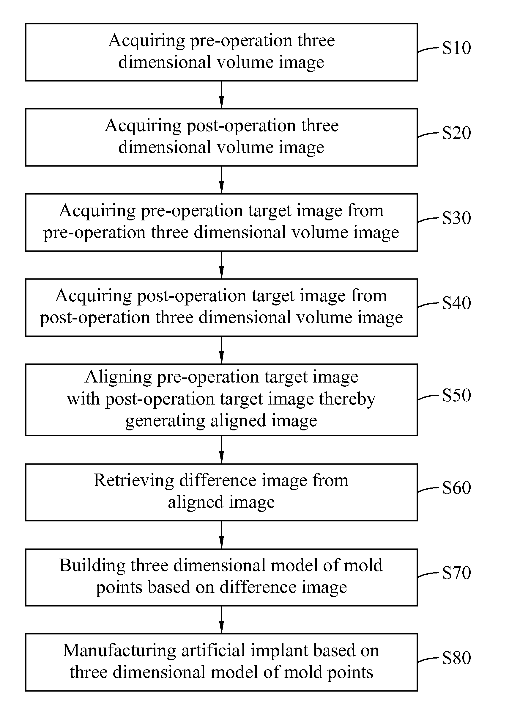
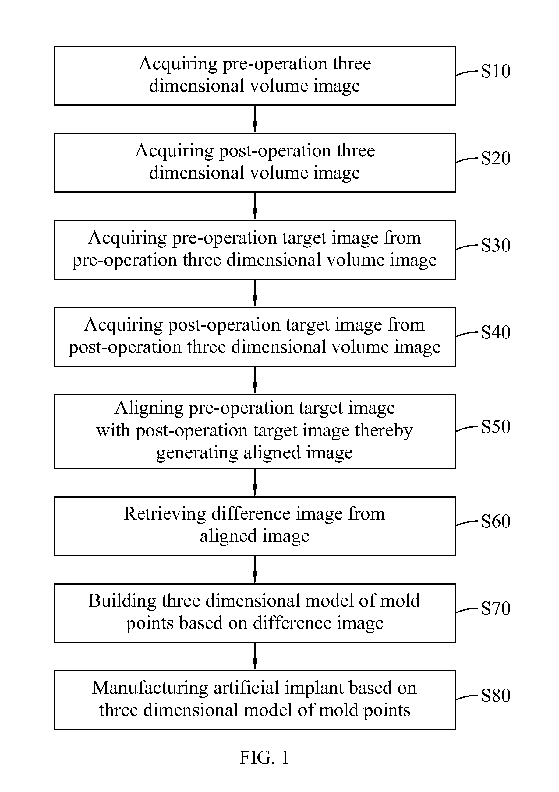
[0041]Refer now to FIG. 1, wherein a flowchart of the method for manufacturing artificial implants according to the present invention is shown. In the Figure, the artificial implant is manufactured by means of the method as the following steps illustrated hereunder:

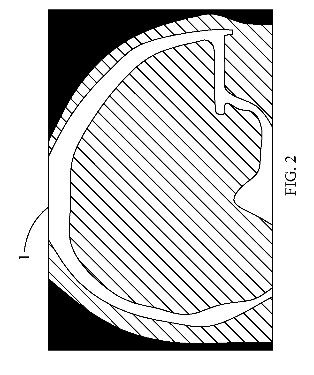
[0042](S10) acquiring the pre-operation three dimensional volume image 1 (as shown in FIG. 2), in which the pre-operation three dimensional volume image 1 comprises the original appearance of a target at the operation portion before incision;

[0043](S20) acquiring the post-operation three dimensional volume image 2 (as shown in FIG. 3), in which the post-operation three dimensional volume image 2 comprises the post-operation appearance of the target at the operation portion after incision, such post-operation appearance having at least one incised part 20 on the target, compared with the original appearance thereof;

[0044](S30) acquiring the pre-operation target image 3 from the pre-operation three dimensional volume image ...


PUM


Abstract

The present invention relates to a method for manufacturing artificial implants, comprising 1) acquiring the pre-operation three dimensional volume image and the post-operation three dimensional volume image of the operation portion, thereby respectively producing the pre-operation target image and the post-operation target image including the target; 2) aligning the pre-operation target image with the post-operation target image so as to generate the aligned image; 3) acquiring the difference image of the incised part in the target based on the aligned image; 4) building the three dimensional model of mold points of the incised part based on the difference image; and 5) manufacturing the artificial implant having the same shape with the incised part based on such three dimensional model of mold points.

Description

BACKGROUND OF THE INVENTION[0001]1. Field of the Invention[0002]The present invention relates to a method for manufacturing artificial implants; in particular, the present invention relates to a method for building a three dimensional model of mold points based on the pre-operation and post-operation images and manufacturing artificial implants in accordance with such three dimensional model of mold points.[0003]2. Description of Related Art[0004]At present, in the field of clinical neurosurgery, under the circumstances of hyper intracranial pressure in patient's brain caused by intracranial tumor, hydrocephalus or other factors, it is common to perform the craniotomy to facilitate effective reduction of the intracranial pressure, and the cranial incisions induced by the craniotomy can be recovered by means of the cranial reconstruction operation. Based on the premises of minimum post-operation infection and desirable restoration of the patient's previous cranial shape, the rebuilt ...

Claims


Application Information

Patent Timeline
IPC IPC(8): G06F19/00
CPCG05B2219/45172G05B2219/49008G06T3/0068G06T2207/30016G06T17/00G06T2207/10072G06T7/0026G06T7/32G06T3/14
Inventor LEE, SHIH TSENGWU, YU-TELIAO, YUAN-LINLU, CHIA-FENGLEE, JIANN-DER
Owner INSIGHTX TECH CORP
Learn More